•
•
•
•
•
•
•
Use a shielded/armored motor cable to comply with EMC emission specications, and connect this cable to both the decou-
pling plate and the motor metal.
Keep motor cable as short as possible to reduce the noise level and leakage currents.
For further details on mounting of the decoupling plate, see VLT® Micro DriveFC 51 Decoupling Mounting Plate Instructions.
Also see the chapter EMC-correct Electrical Installation in the VLT® Micro DriveFC 51 Design Guide.
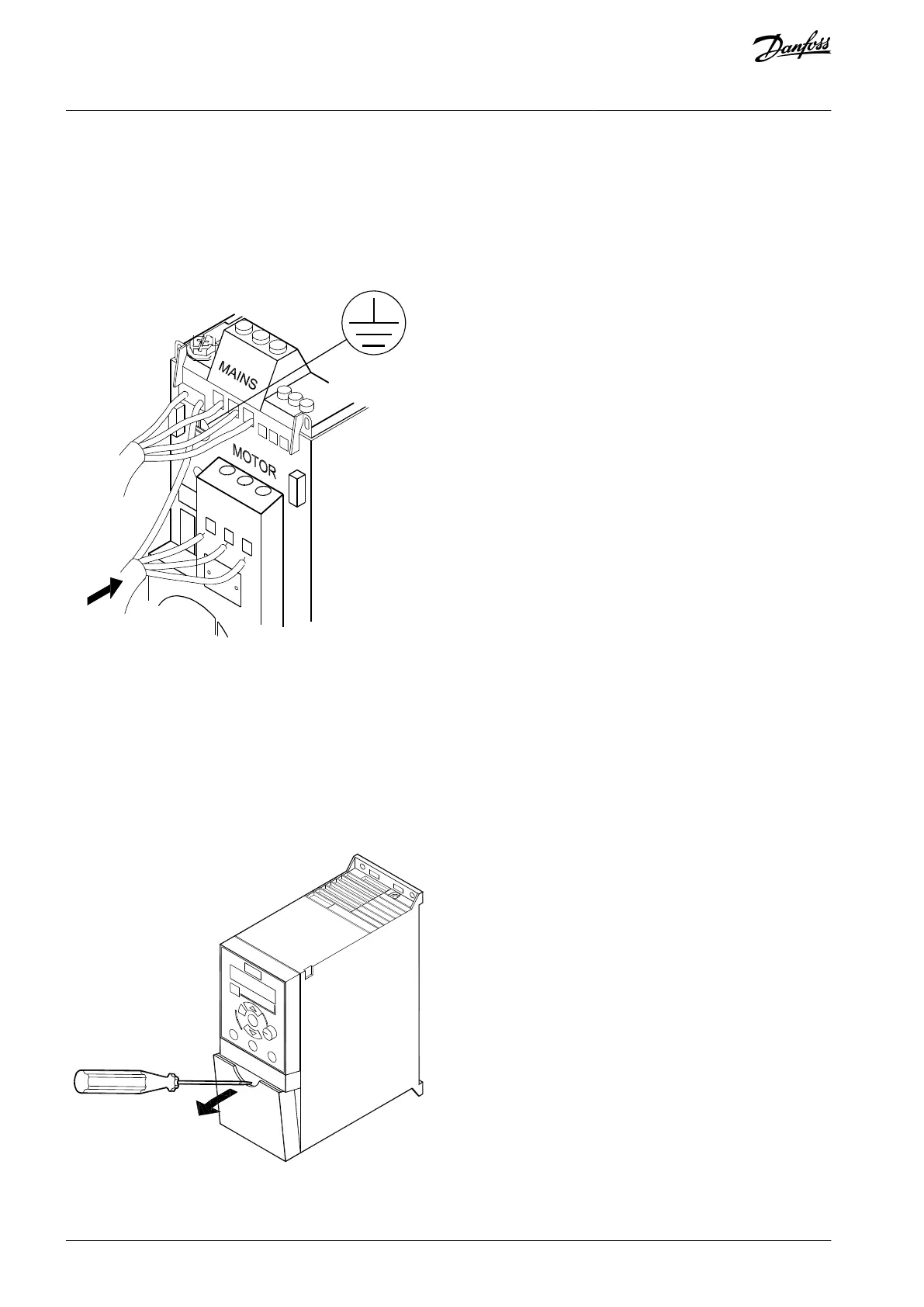
Mounting of Ground Cable, Mains, and Motor Wires
Illustration 2: Mounting of Ground Cable, Mains, and Motor Wires
Mount the ground wires to PE terminal.
Connect motor to terminals U, V, and W.
Mount mains supply to terminals L1/L, L2, and L3/N (3-phase) or L1/L and L3/N (single-phase) and tighten.
3.7 Control Terminals
All control cable terminals are located underneath the terminal cover in front of the drive. Remove the terminal cover using a screw-
driver.
Illustration 3: Removing Terminal Cover
AQ348848915086en-000101 / 130R094312 | Danfoss A/S © 2020.09
Installation
VLT® Micro Drive FC 51
Operating Guide

 Loading...


