N O T I C E
See the back of the terminal cover for outlines of control terminals and switches.
N O T I C E
Do not operate switches with power on the drive.
N O T I C E
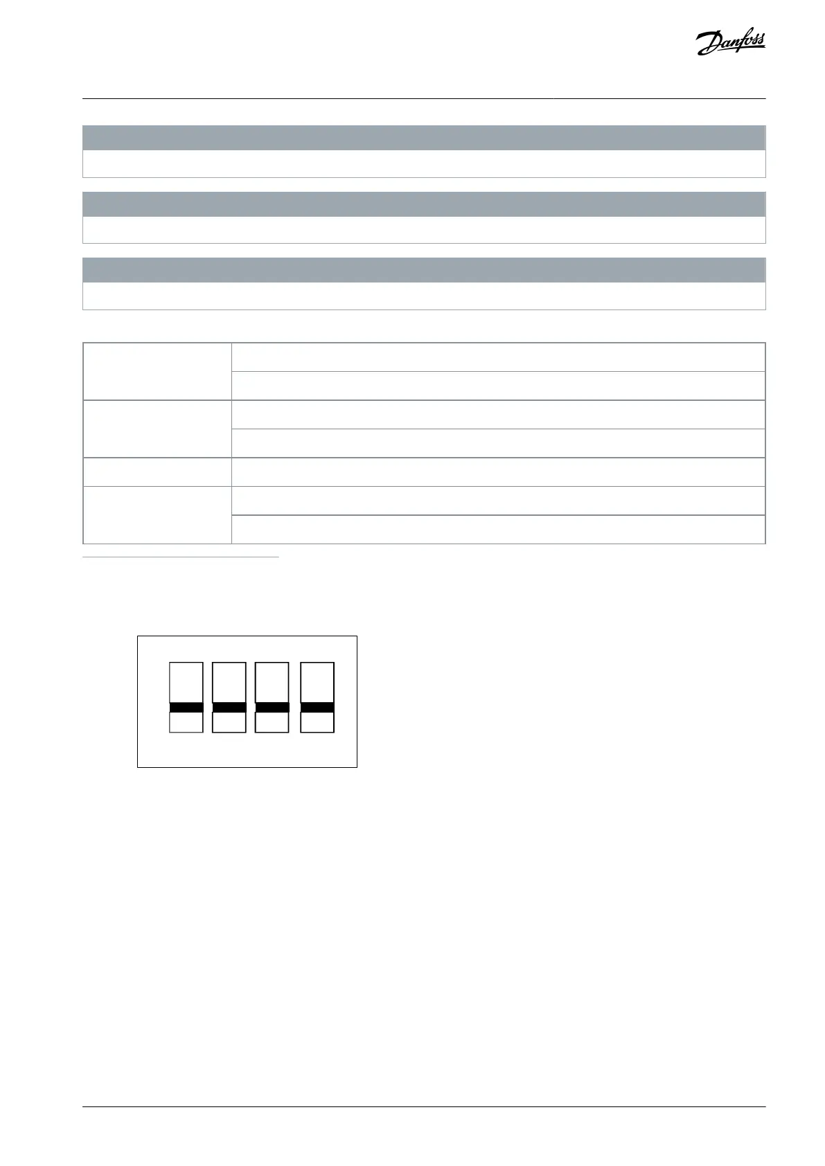
Set parameter 6-19 Terminal 53 Mode according to Switch 4 position.
Table 5: Settings for S200 Switches 1–4
O=PNP terminal 18, 19, 27, and 33
(1)
On=NPN terminal 18, 19, 27, and 33
1
This is the default setting.
e30ba474.10
ON
OFF
1 2 43
PNP/NPN
PNP/NPN
U/I
Illustration 4: S200 Switches 1–4
The following illustration shows all control terminals of the drive. Applying start (terminal 18) and an analog reference (terminal 53
or 60) make the drive run.
AQ348848915086en-000101 / 130R0943 | 13Danfoss A/S © 2020.09
Installation
VLT® Micro Drive FC 51
Operating Guide

 Loading...


