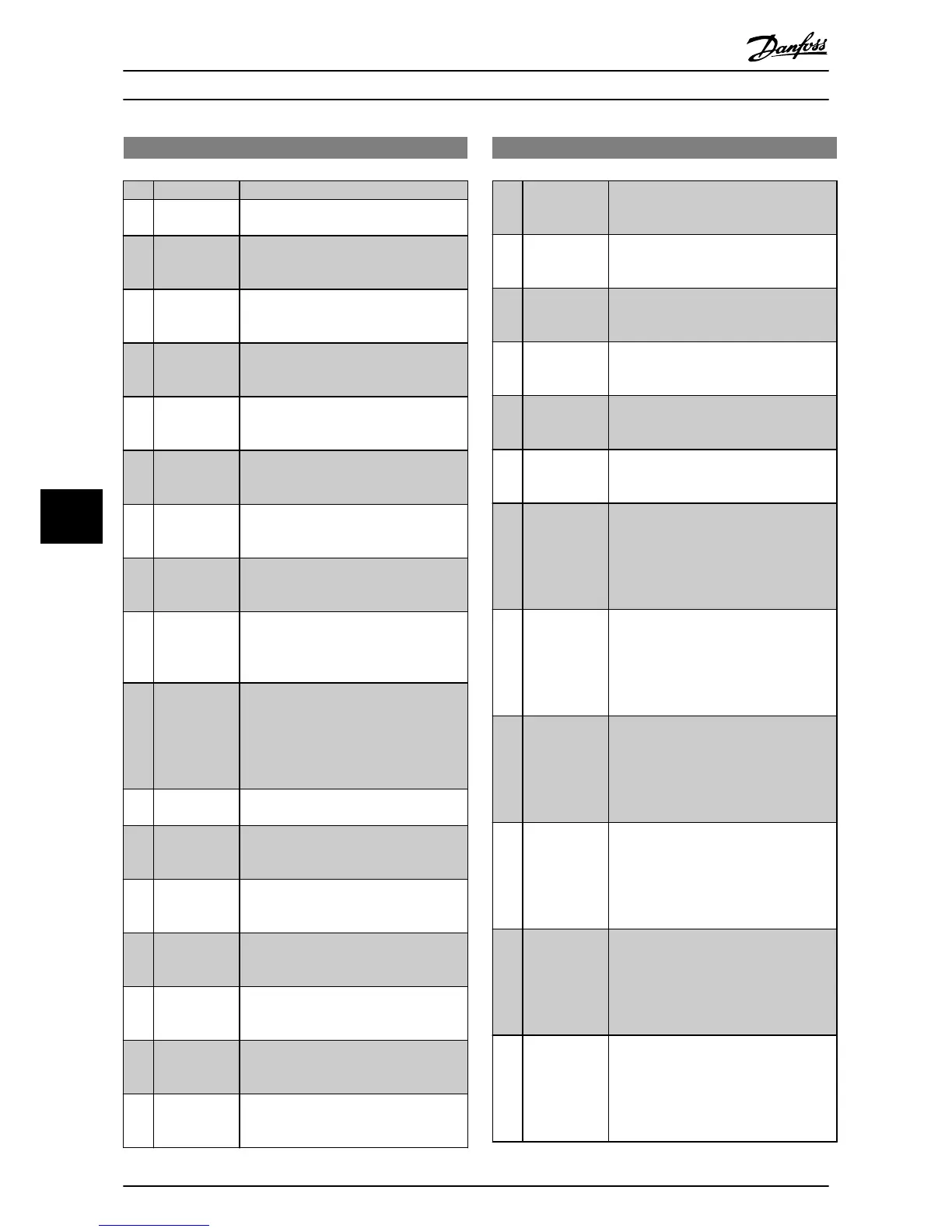
8-13 Configurable Status Word STW
Option: Function:
[2] Alarm 68 Only Only set in case of an Alarm 68.
[3] Trip excl.
Alarm 68
Set in case of a trip, except if Alarm 68
executes the trip.
[10] T18 DI status. The bit indicates the status of terminal 18.
“0” indicates that the terminal is low
“1” indicates that the terminal is high
[11] T19 DI status. The bit indicates the status of terminal 19.
“0” indicates that the terminal is low
“1” indicates that the terminal is high
[12] T27 DI status. The bit indicates the status of terminal 27.
“0” indicates that the terminal is low
“1” indicates that the terminal is high
[13] T29 DI status. The bit indicates the status of terminal 29.
“0” indicates that the terminal is low
“1” indicates that the terminal is high
[14] T32 DI status. The bit indicates the status of terminal 32.
“0” indicates that the terminal is low
“1” indicates that the terminal is high
[15] T33 DI status. The bit indicates the status of terminal 33.
“0” indicates that the terminal is low
“1” indicates that the terminal is high
[16] T37 DI status The bit indicates the status of terminal 37.
”0” indicates T37 is low (safe stop)
“1” indicates T37 is high (normal)
[21] Thermal
warning
The thermal warning turns on when the
temperature exceeds the limit in the
motor, the frequency converter, the brake
resistor, or the thermistor.
[30] Brake fault
(IGBT)
Output is Logic ‘1’ when the brake IGBT is
short-circuited. Use this function to protect
the frequency converter if there is a fault
on the brake modules. Use the output/
relay to cut out the main voltage from the
frequency converter.
[40] Out of ref.
range
[60] Comparator 0
See parameter group 13-1* Comparators. If
Comparator 0 is evaluated as TRUE, the
output goes high. Otherwise, it is low.
[61] Comparator 1
See parameter group 13-1* Comparators. If
Comparator 1 is evaluated as TRUE, the
output goes high. Otherwise, it is low.
[62] Comparator 2
See parameter group 13-1* Comparators. If
Comparator 2 is evaluated as TRUE, the
output goes high. Otherwise, it is low.
[63] Comparator 3
See parameter group 13-1* Comparators. If
Comparator 3 is evaluated as TRUE, the
output goes high. Otherwise, it is low.
[64] Comparator 4
See parameter group 13-1* Comparators. If
Comparator 4 is evaluated as TRUE, the
output goes high. Otherwise, it is low.
[65] Comparator 5
See parameter group 13-1* Comparators. If
Comparator 5 is evaluated as TRUE, the
output goes high. Otherwise, it is low.
8-13 Configurable Status Word STW
Option: Function:
[70] Logic Rule 0
See parameter group 13-4* Logic Rules. If
Logic Rule 0 is evaluated as TRUE, the
output goes high. Otherwise, it is low.
[71] Logic Rule 1
See parameter group 13-4* Logic Rules. If
Logic Rule 1 is evaluated as TRUE, the
output goes high. Otherwise, it is low.
[72] Logic Rule 2
See parameter group 13-4* Logic Rules. If
Logic Rule 2 is evaluated as TRUE, the
output goes high. Otherwise, it is low.
[73] Logic Rule 3
See parameter group 13-4* Logic Rules. If
Logic Rule 3 is evaluated as TRUE, the
output goes high. Otherwise, it is low.
[74] Logic Rule 4
See parameter group 13-4* Logic Rules. If
Logic Rule 4 is evaluated as TRUE, the
output goes high. Otherwise, it is low.
[75] Logic Rule 5
See parameter group 13-4* Logic Rules. If
Logic Rule 5 is evaluated as TRUE, the
output goes high. Otherwise, it is low.
[80] SL Digital
Output A
See 13-52 SL Controller Action. The output
goes high whenever the Smart Logic
Action [38] Set digital out A high is
executed. The output goes low whenever
the Smart Logic Action [32] Set digital out
A low is executed.
[81] SL Digital
Output B
See 13-52 SL Controller Action. The input
goes high whenever the Smart Logic
Action [39] Set digital out B high is
executed. The input goes low whenever
the Smart Logic Action [33] Set digital out B
low is executed.
[82] SL Digital
Output C
See 13-52 SL Controller Action. The input
goes high whenever the Smart Logic
Action [40] Set digital out C high is
executed. The input goes low whenever
the Smart Logic Action [34] Set digital out
C low is executed.
[83] SL Digital
Output D
See 13-52 SL Controller Action. The input
goes high whenever the Smart Logic
Action [41] Set digital out D high is
executed. The input goes low whenever
the Smart Logic Action [35] Set digital out
D low is executed.
[84] SL Digital
Output E
See 13-52 SL Controller Action. The input
goes high whenever the Smart Logic
Action [42] Set digital out E high is
executed. The input goes low whenever
the Smart Logic Action [36] Set digital out E
low is executed.
[85] SL Digital
Output F
See 13-52 SL Controller Action. The input
goes high whenever the Smart Logic
Action [43] Set digital out F high is
executed. The input goes low whenever
the Smart Logic Action [37] Set digital out F
low is executed.
Parameters Operating Instructions
44 Danfoss A/S © Rev. 2014-02-27 All rights reserved. MG90U302
88