Response
The register data in the response message are packed as
two bytes per register, with the binary contents right
justified within each byte. For each register, the first byte
contains the high order bits and the second contains the
low order bits.
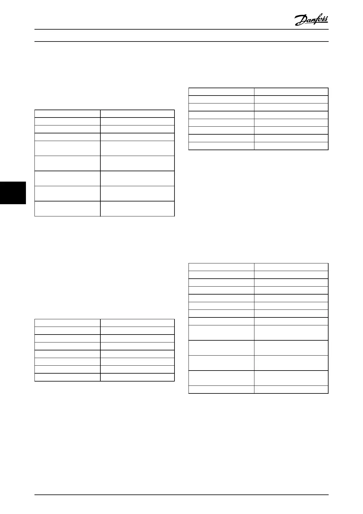
Field Name Example (HEX)
Slave Address 01
Function 03
Byte Count 04
Data HI
(Register 3030)
00
Data LO
(Register 3030)
16
Data HI
(Register 3031)
E3
Data LO
(Register 3031)
60
Error Check
(CRC)
-
Table 7.29
7.8.5 Preset Single Register (06 HEX)
Description
This function presets a value into a single holding register.
Query
The query message specifies the register reference to be
preset. Register addresses start at zero, i.e. register 1 is
addressed as 0.
Example: Write to 1-00 Configuration Mode, register 1000.
Field Name Example (HEX)
Slave Address 01
Function 06
Register Address HI 03 (Register address 999)
Register Address LO E7 (Register address 999)
Preset Data HI 00
Preset Data LO 01
Error Check (CRC) -
Table 7.30
Response
The normal response is an echo of the query, returned
after the register contents have been passed.
Field Name Example (HEX)
Slave Address 01
Function 06
Register Address HI 03
Register Address LO E7
Preset Data HI 00
Preset Data LO 01
Error Check (CRC) -
Table 7.31
7.8.6 Preset Multiple Registers (10 HEX)
Description
This function presets values into a sequence of holding
registers.
Query
The query message specifies the register references to be
preset. Register addresses start at zero, i.e. register 1 is
addressed as 0. Example of a request to preset two
registers (set parameter 1-24=738 (7.38 A)):
Field Name Example (HEX)
Slave Address 01
Function 10
Starting Address HI 04
Starting Address LO D7
No. of Registers HI 00
No. of registers LO 02
Byte Count 04
Write Data HI
(Register 4: 1049)
00
Write Data LO
(Register 4: 1049)
00
Write Data HI
(Register 4: 1050)
02
Write Data LO
(Register 4: 1050)
E2
Error Check (CRC) -
Table 7.32
RS-485 Installation and Set...
VLT
®
Refrigeration Drive Design Guide
100 MG16G102 - VLT
®
is a registered Danfoss trademark
7