Furthermore, the terminal screw must be retightened after
two days due to the softness of the aluminium. It is crucial
to keep the connection a gas tight joint, otherwise the
aluminium surface will oxidize again.
5.2.5 Removal of Knockouts for Extra
Cables
1. Remove cable entry from the frequency converter
(Avoiding foreign parts falling into the frequency
converter when removing knockouts)
2. Cable entry has to be supported around the
knockout you intend to remove.
3. The knockout can now be removed with a strong
mandrel and a hammer.
4. Remove burrs from the hole.
5. Mount Cable entry on frequency converter.
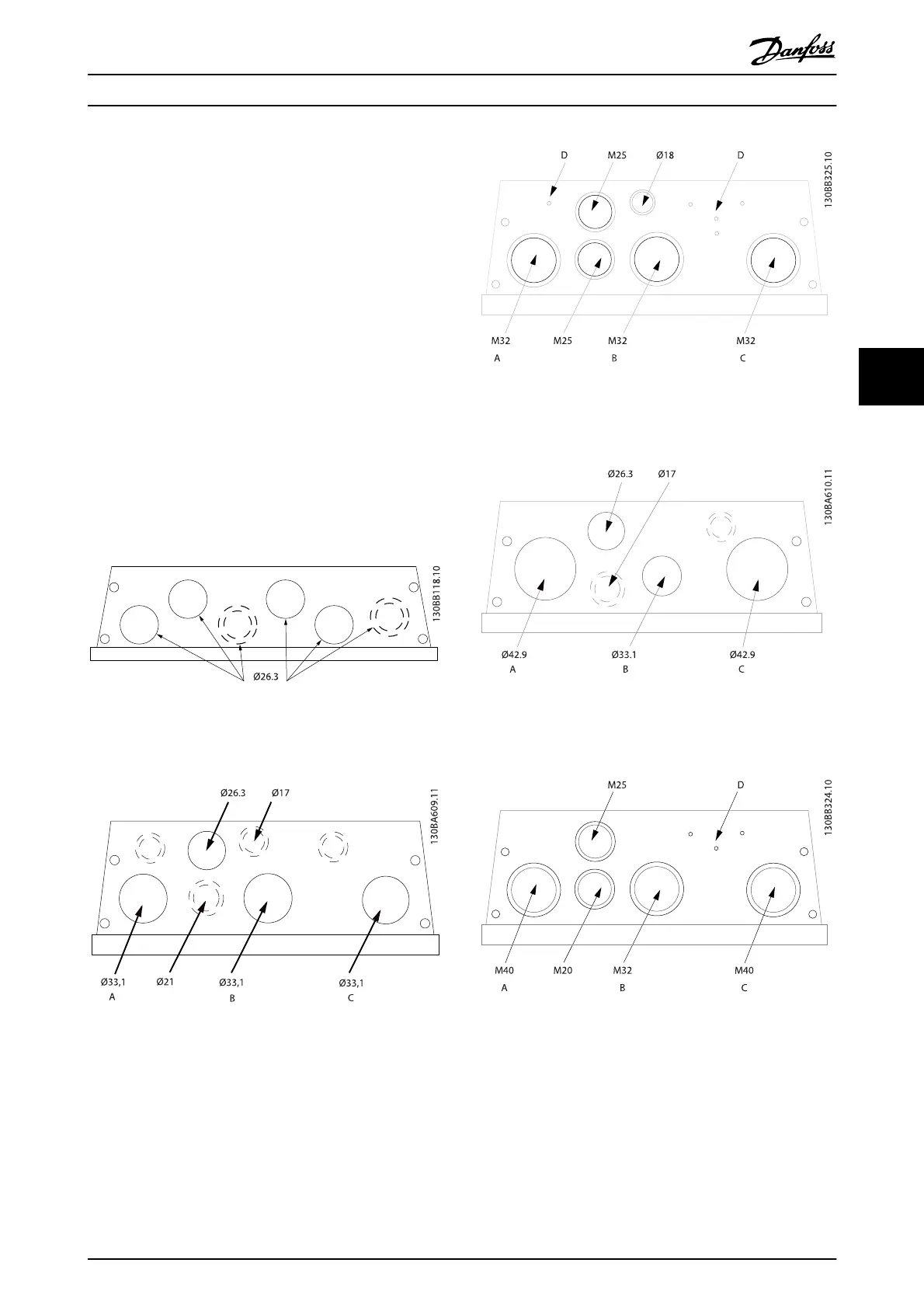
5.2.6 Enclosure Knock-outs
Illustration 5.7 Cable entry holes for enclosure A5. The
suggested use of the holes are purely recommendations and
other solutions are possible.
Illustration 5.8 Cable entry holes for enclosure B1. The suggested
use of the holes are purely recommendations and other
solutions are possible.
Illustration 5.9 Cable entry holes for enclosure B1. The suggested
use of the holes are purely recommendations and other
solutions are possible.
Illustration 5.10 Cable entry holes for enclosure B2. The
suggested use of the holes are purely recommendations and
other solutions are possible.
Illustration 5.11 Cable entry holes for enclosure B2. The
suggested use of the holes are purely recommendations and
other solutions are possible.
How to Install
VLT
®
Refrigeration Drive Design Guide
MG16G102 - VLT
®
is a registered Danfoss trademark 65
5