NOTE
Indicates highlighted information that should be regarded
with attention to avoid mistakes or operate equipment at
less than optimal performance.
*
Indicates default setting
Table 1.2
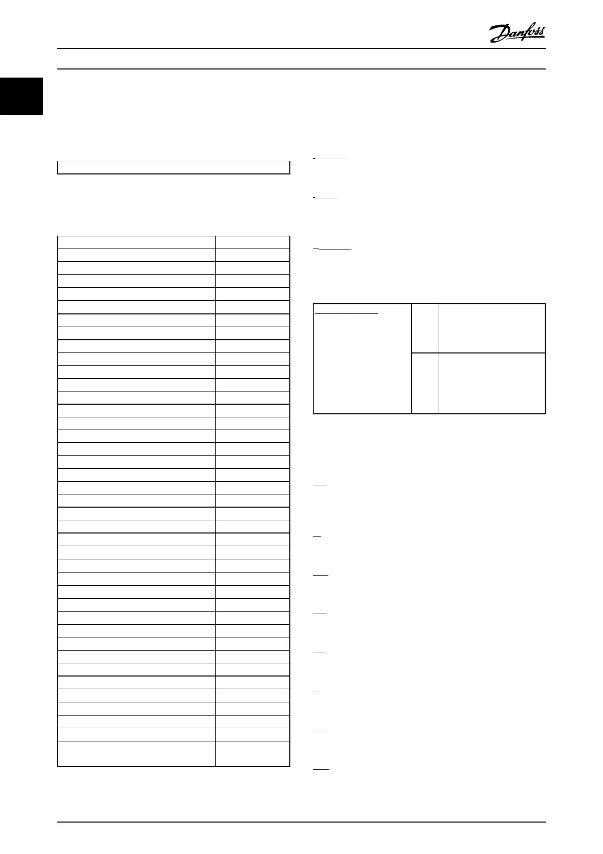
1.1.6 Abbreviations
Alternating current AC
American wire gauge AWG
Ampere/AMP A
Automatic Motor Adaptation AMA
Current limit I
LIM
Degrees Celsius
°
C
Direct current DC
Drive Dependent D-TYPE
Electro Magnetic Compatibility EMC
Electronic Thermal Relay ETR
Frequency converter FC
Gram g
Hertz Hz
Horsepower hp
Kilohertz kHz
Local Control Panel LCP
Meter m
Millihenry Inductance mH
Milliampere mA
Millisecond ms
Minute min
Motion Control Tool MCT
Nanofarad nF
Newton Meters Nm
Nominal motor current I
M,N
Nominal motor frequency f
M,N
Nominal motor power P
M,N
Nominal motor voltage U
M,N
Permanent Magnet motor PM motor
Protective Extra Low Voltage PELV
Printed Circuit Board PCB
Rated Inverter Output Current I
INV
Revolutions Per Minute RPM
Regenerative terminals Regen
Second s
Synchronous Motor Speed n
s
Torque limit T
LIM
Volts V
The maximum output current I
VLT,MAX
The rated output current supplied by the
frequency converter
I
VLT,N
Table 1.3
1.1.7 Definitions
Drive:
I
DRIVE,MAX
The maximum output current.
I
DRIVE,N
The rated output current supplied by the frequency
converter.
U
DRIVE, MAX
The maximum output voltage.
Input:
Control command
Start and stop the
connected motor with the
LCP or the digital inputs.
Functions are divided into
two groups.
Functions in group 1 have
higher priority than
functions in group 2.
Group
1
Reset, Coasting stop, Reset
and Coasting stop, Quick-
stop, DC braking, Stop and
the "Off" key.
Group
2
Start, Pulse start, Reversing,
Start reversing, Jog and
Freeze output
Table 1.4
Motor:
f
JOG
The motor frequency when the jog function is activated
(via digital terminals).
f
M
The motor frequency.
f
MAX
The maximum motor frequency.
f
MIN
The minimum motor frequency.
f
M,N
The rated motor frequency (nameplate data).
I
M
The motor current.
I
M,N
The rated motor current (nameplate data).
n
M,N
The rated motor speed (nameplate data).
How to Read this Design Gui...
VLT
®
Refrigeration Drive Design Guide
6 MG16G102 - VLT
®
is a registered Danfoss trademark
1