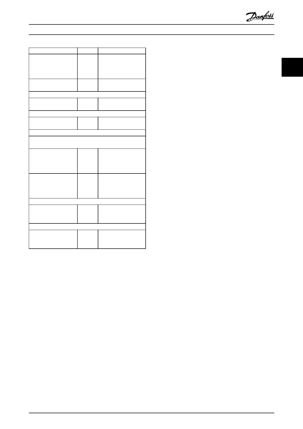
Function Par. no. Setting
Set acceptable limits for
the motor speed.
4-12
4-14
4-19
10 Hz, Motor min speed
50 Hz, Motor max speed
50 Hz, Drive max output
frequency
Switch from open loop to
closed loop.
1-00 [3] Closed Loop
4) Configure the feedback to the PID controller.
Select the appropriate
reference/feedback unit.
20-12 [71] Bar
5) Configure the set-point reference for the PID controller.
Set acceptable limits for
the set-point reference.
20-13
20-14
0 Bar
10 Bar
Choose current or voltage by switches S201 / S202
6) Scale the analog inputs used for set-point reference and
feedback.
Scale Analog Input 53 for
the pressure range of the
potentiometer (0 - 10 Bar,
0 - 10 V).
6-10
6-11
6-14
6-15
0 V
10 V (default)
0 Bar
10 Bar
Scale Analog Input 54 for
pressure sensor (0 - 10
Bar, 4 - 20 mA)
6-22
6-23
6-24
6-25
4 mA
20 mA (default)
0 Bar
10 Bar
7) Tune the PID controller parameters.
Adjust the drive’s Closed
Loop Controller, if
needed.
20-93
20-94
See Optimization of the
PID Controller, below.
8) Finished!
Save the parameter
setting to the LCP for safe
keeping
0-50 [1] All to LCP
Table 2.8
2.8.10 Tuning the Drive Closed Loop
Controller
Once the frequency converter's Closed Loop Controller has
been set up, the performance of the controller should be
tested. In many cases, its performance may be acceptable
using the default values of 20-93 PID Proportional Gain and
20-94 PID Integral Time. However, in some cases it may be
helpful to optimize these parameter values to provide
faster system response while still controlling speed
overshoot.
2.8.11 Manual PID Adjustment
1. Start the motor
2. Set 20-93 PID Proportional Gain to 0.3 and
increase it until the feedback signal begins to
oscillate. If necessary, start and stop the drive or
make step changes in the set-point reference to
attempt to cause oscillation. Next reduce the PID
Proportional Gain until the feedback signal
stabilizes. Then reduce the proportional gain by
40-60%.
3.
Set 20-94 PID Integral Time to 20 s and reduce it
until the feedback signal begins to oscillate. If
necessary, start and stop the drive or make step
changes in the set-point reference to attempt to
cause oscillation. Next, increase the PID Integral
Time until the feedback signal stabilizes. Then
increase of the Integral Time by 15-50%.
4. 20-95 PID Differentiation Time should only be used
for very fast-acting systems. The typical value is
25% of 20-94 PID Integral Time. The differential
function should only be used when the setting of
the proportional gain and the integral time has
been fully optimized. Make sure that oscillations
of the feedback signal are sufficiently dampened
by the low-pass filter for the feedback signal
(parameters 6-16, 6-26, 5-54 or 5-59 as required).
2.9 General Aspects of EMC
2.9.1 General Aspects of EMC Emissions
Electrical interference is usually conducted at frequencies
in the range 150 kHz to 30 MHz. Airborne interference
from the frequency converter system in the range 30 MHz
to 1 GHz is generated from the inverter, motor cable, and
the motor.
As shown in Illustration 2.20, capacitive currents in the
motor cable coupled with a high dU/dt from the motor
voltage generate leakage currents.
The use of a screened motor cable increases the leakage
current (see Illustration 2.20) because screened cables have
higher capacitance to earth than unscreened cables. If the
leakage current is not filtered, it will cause greater
interference on the mains in the radio frequency range
below approximately 5 MHz. Since the leakage current (I
1
)
is carried back to the unit through the screen (I
3
), there
will in principle only be a small electro-magnetic field (I
4
)
from the screened motor cable according to the below
figure.
The screen reduces the radiated interference but increases
the low-frequency interference on the mains. The motor
cable screen must be connected to the frequency
converter enclosure as well as on the motor enclosure. This
is best done by using integrated screen clamps so as to
avoid twisted screen ends (pigtails). These increase the
screen impedance at higher frequencies, which reduces the
screen effect and increases the leakage current (I
4
).
If a screened cable is used for fieldbus, relay, control cable,
signal interface and brake, the screen must be mounted on
the enclosure at both ends. In some situations, however, it
Introduction
VLT
®
Refrigeration Drive Design Guide
MG16G102 - VLT
®
is a registered Danfoss trademark 25
2