5How to Install
5.1 Mechanical Installation
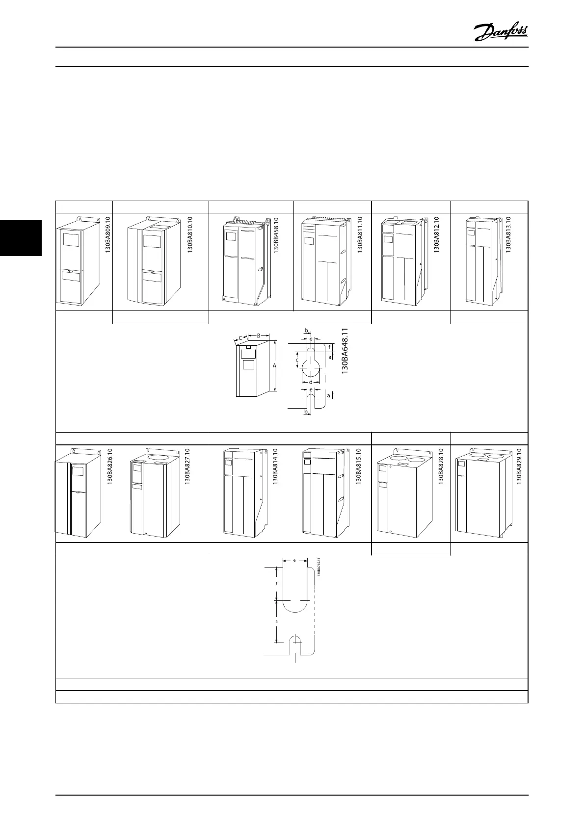
5.1.1 Mechanical Front Views
A2 A3 A4 A5 B1 B2
IP20/21* IP20/21* IP55/66 IP55/66 IP21/55/66 IP21/55/66
Top and bottom mounting holes.
B3 B4 C1 C2 C3 C4
IP20/21* IP20/21* IP21/55/66 IP21/55/66 IP20/21* IP20/21*
Top and bottom mounting holes. (B4+C3+C4 only)
Accessory bags containing necessary brackets, screws and connectors are included with the frequency converter upon delivery.
* IP21 can be established with a kit as described in 3.1.14 IP21/IP41/ TYPE 1 Enclosure Kit.
Table 5.1
How to Install
VLT
®
Refrigeration Drive Design Guide
56 MG16G102 - VLT
®
is a registered Danfoss trademark
5