4. Opto-coupler, brake module.
5. Internal inrush, RFI, and temperature
measurement circuits.
6. Custom relays.
7. Mechanical brake.
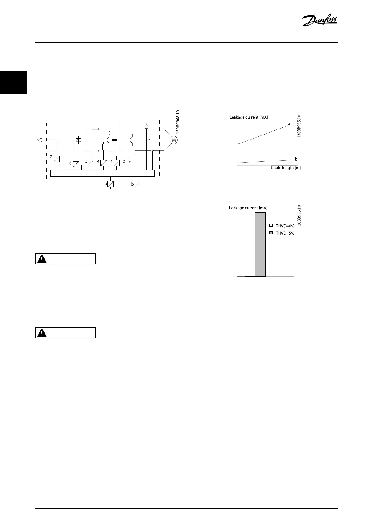
Illustration 2.22 Galvanic Isolation
The functional galvanic isolation (a and b on
Illustration 2.22) is for the 24 V back-up option and for the
RS-485 standard bus interface.
WARNING
Installation at high altitude:
380-480 V, enclosure A, B and C: At altitudes above 2 km,
please contact Danfoss regarding PELV.
380-480 V, enclosure D: At altitudes above 3 km, please
contact Danfoss regarding PELV.
525-690 V: At altitudes above 2 km, please contact Danfoss
regarding PELV.
WARNING
Touching the electrical parts could be fatal - even after the
equipment has been disconnected from mains.
Also make sure that other voltage inputs have been
disconnected, such as load sharing (linkage of DC
intermediate circuit), as well as the motor connection for
kinetic back-up.
Before touching any electrical parts, wait at least the
amount of time indicated in 2.1.2 Caution.
Shorter time is allowed only if indicated on the nameplate
for the specific unit.
2.11 Earth Leakage Current
Follow national and local codes regarding protective
earthing of equipment with a leakage current > 3,5 mA.
Frequency converter technology implies high frequency
switching at high power. This will generate a leakage
current in the earth connection. A fault current in the
frequency converter at the output power terminals might
contain a DC component which can charge the filter
capacitors and cause a transient earth current.
The earth leakage current is made up of several contri-
butions and depends on various system configurations
including RFI filtering, screened motor cables, and
frequency converter power.
Illustration 2.23 Cable Length and Power Size Influence on
Leakage Current. Pa > Pb
Illustration 2.24 Line Distortion Influences Leakage Current
NOTE
When a filter is used, turn off 14-50 RFI Filter when
charging the filter, to avoid that a high leakage current
makes the RCD switch.
EN/IEC61800-5-1 (Power Drive System Product Standard)
requires special care if the leakage current exceeds 3.5mA.
Earth grounding must be reinforced in one of the
following ways:
•
Earth ground wire (terminal 95) of at least 10
mm
2
•
Two separate earth ground wires both complying
with the dimensioning rules
See EN/IEC61800-5-1 and EN50178 for further information.
Introduction
VLT
®
Refrigeration Drive Design Guide
32 MG16G102 - VLT
®
is a registered Danfoss trademark
2