5.2 Electrical Installation
5.2.1 Cables General
NOTE
For the VLT
®
Refrigeration Drive FCR 103 High Power series
mains and motor connections, see VLT
®
Refrigeration Drive
110-250 kW, MG16F.
NOTE
Cables General
All cabling must comply with national and local
regulations on cable cross-sections and ambient
temperature. Copper (60/75 °C) conductors are
recommended.
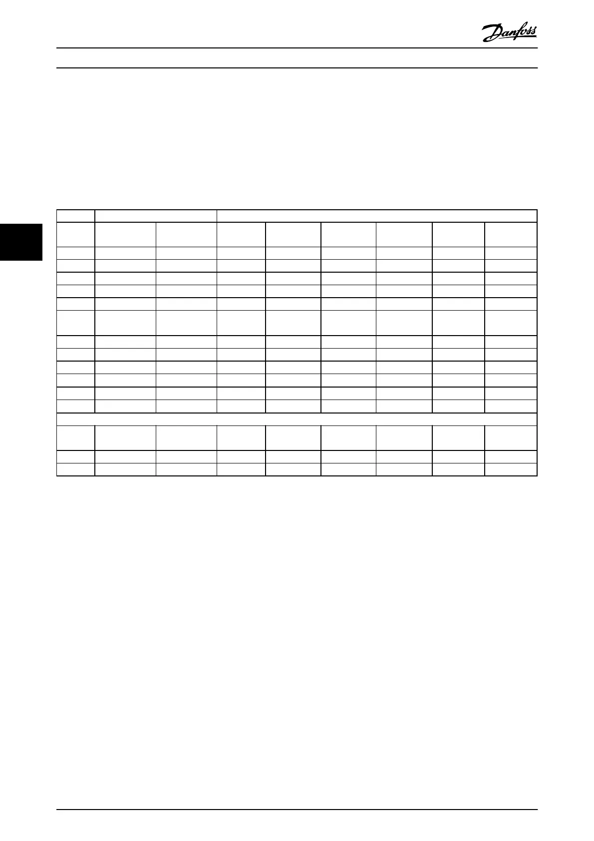
Power [kW] Torque [Nm]
Enclo-
sure
200-240
V
380-480
V
Mains Motor
DC
connection
Brake Earth Relay
A2 1.1-3.0 1.1-4.0 1.8 1.8 1.8 1.8 3 0.6
A3 3.7 5.5-7.5 1.8 1.8 1.8 1.8 3 0.6
A4 1.1-2.2 1.1-4 kW 1.8 1.8 1.8 1.8 3 0.6
A5 1.1-3.7 1.1-7.5 1.8 1.8 1.8 1.8 3 0.6
B1 5.5-11 11-18.5 1.8 1.8 1.5 1.5 3 0.6
B2
-
15
22
30
4.5
4.5
2)
4.5
4.5
2)
3.7
3.7
3.7
3.7
3
3
0.6
0.6
B3 5.5-11 11-18.5 1.8 1.8 1.8 1.8 3 0.6
B4 11-18.5 18.5-37 4.5 4.5 4.5 4.5 3 0.6
C1 18.5-30 37-55 10 10 10 10 3 0.6
C2 37-45 75-90
14/24
1)
14/24
1)
14 14 3 0.6
C3 18.5-30 37-55 10 10 10 10 3 0.6
C4 30-45 55-90
14/24
1)
14/24
1)
14 14 3 0.6
High Power
Enclo-
sure
380-480
V
Mains Motor
DC
connection
Brake Earth Relay
D1/D3 110-132 19 19 9.6 9.6 19 0.6
D2/D4 160-250 19 19 9.6 9.6 19 0.6
Table 5.7 Tightening of Terminals
1) For different cable dimensions x/y, where x ≤ 95 mm
2
and y ≥ 95
mm
2
2) Cable dimensions above 18.5 kW
≥
35 mm
2
and below 22 kW
≤
10 mm
2
How to Install
VLT
®
Refrigeration Drive Design Guide
62 MG16G102 - VLT
®
is a registered Danfoss trademark
5