1. Use a clamp from the accessory bag to connect
the screen to the frequency converter decoupling
plate for control cables.
See section entitled 5.7.3 Earthing of Screened/Armoured
Control Cables for the correct termination of control cables.
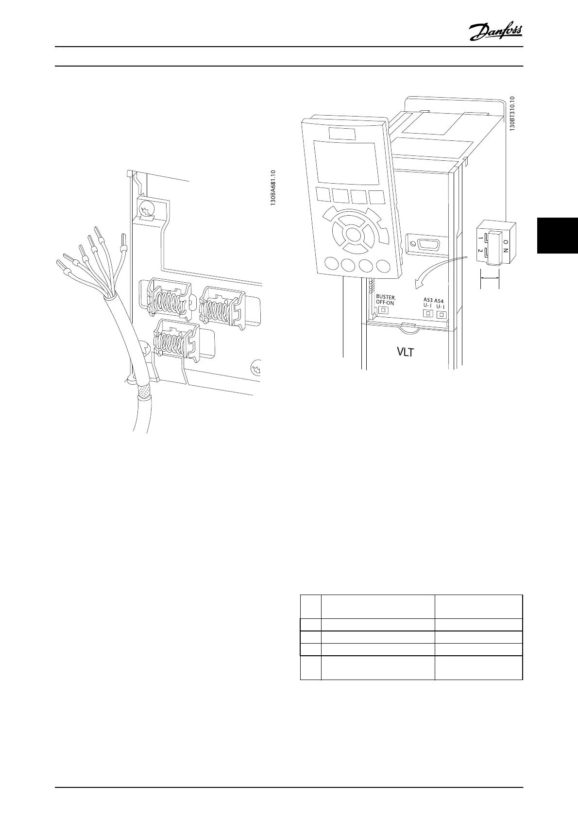
Illustration 5.24
5.2.13 Switches S201, S202, and S801
Switches S201 (A53) and S202 (A54) are used to select a
current (0-20 mA) or a voltage (0 to 10 V) configuration of
the analog input terminals 53 and 54 respectively.
Switch S801 (BUS TER.) can be used to enable termination
on the RS-485 port (terminals 68 and 69).
See Illustration 5.23
Default setting:
S201 (A53) = OFF (voltage input)
S202 (A54) = OFF (voltage input)
S801 (Bus termination) = OFF
NOTE
It is recommended to only change switch position at
power off.
Illustration 5.25
5.3 Final Set-Up and Test
To test the set-up and ensure that the frequency converter
is running, follow these steps.
Step 1. Locate the motor name plate
The motor is either star- (Y) or delta- connected (Δ). This
information is located on the motor name plate data.
Step 2. Enter the motor name plate data in this parameter
list.
To access this list first press the [Quick Menu] key then
select “Q2 Quick Setup”.
1. Motor Power [kW]
or Motor Power [HP]
1-20 Motor Power [kW]
1-21 Motor Power [HP]
2. Motor Voltage 1-22 Motor Voltage
3. Motor Frequency 1-23 Motor Frequency
4. Motor Current 1-24 Motor Current
5. Motor Nominal Speed 1-25 Motor Nominal
Speed
Table 5.10
Step 3. Activate the Automatic Motor Adaptation (AMA)
Performing an AMA will ensure optimum performance. The
AMA measures the values from the motor model
equivalent diagram.
How to Install
VLT
®
Refrigeration Drive Design Guide
MG16G102 - VLT
®
is a registered Danfoss trademark 71
5