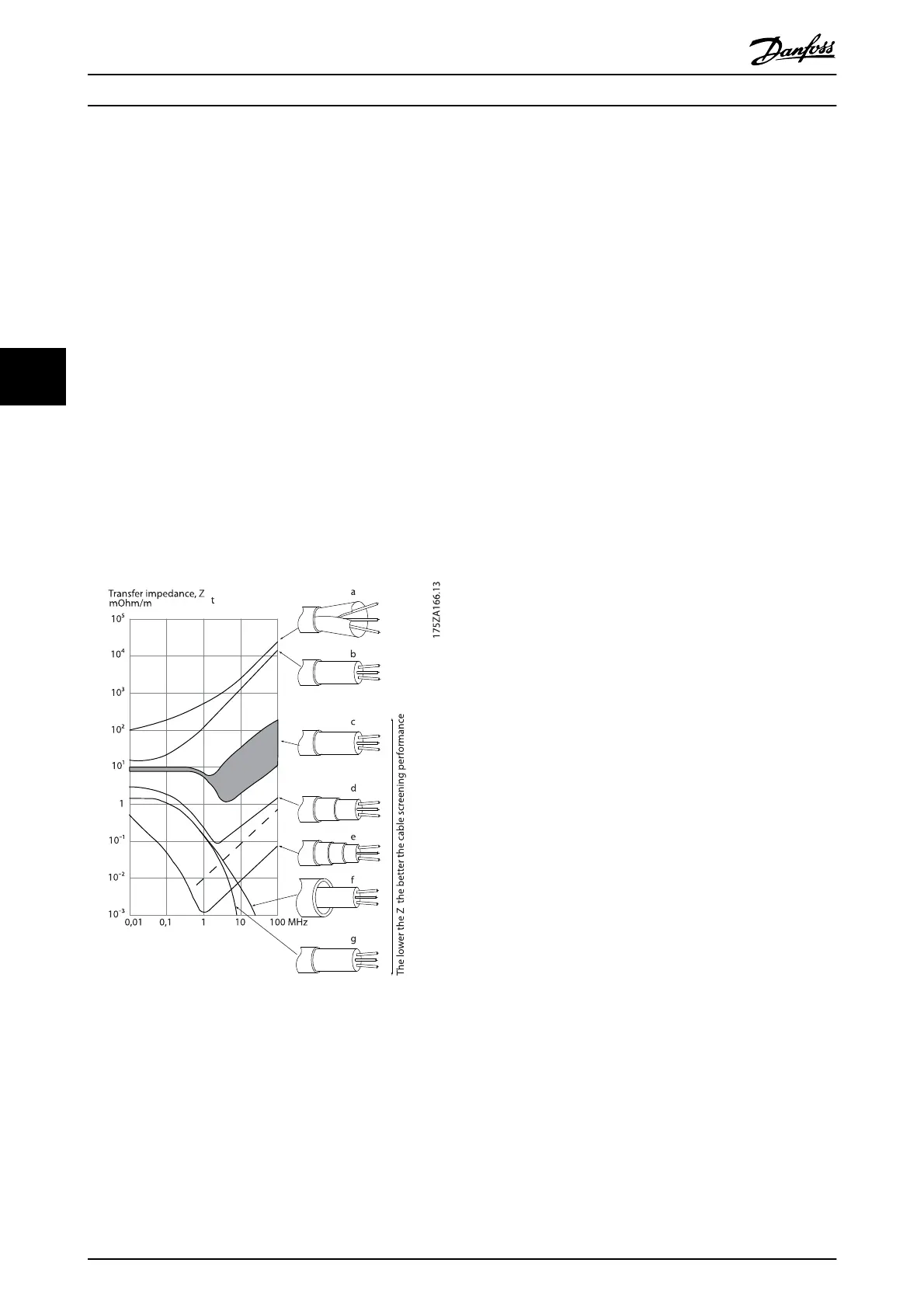
Transfer impedance (Z
T
) can be assessed on the basis of
the following factors:
- The conductibility of the screen material.
- The contact resistance between the individual
screen conductors.
- The screen coverage, i.e. the physical area of the
cable covered by the screen - often stated as a
percentage value.
- Screen type, i.e. braided or twisted pattern.
a. Aluminium-clad with copper wire.
b. Twisted copper wire or armoured steel wire cable.
c. Single-layer braided copper wire with varying
percentage screen coverage.
This is the typical Danfoss reference cable.
d. Double-layer braided copper wire.
e. Twin layer of braided copper wire with a
magnetic, screened/armoured intermediate layer.
f. Cable that runs in copper tube or steel tube.
g. Lead cable with 1.1 mm wall thickness.
Illustration 5.33
5.7.3 Earthing of Screened/Armoured
Control Cables
Generally speaking, control cables must be braided
screened/armoured and the screen must be connected by
means of a cable clamp at both ends to the metal cabinet
of the unit.
The drawing below indicates how correct earthing is
carried out and what to do if in doubt.
a. Correct earthing
Control cables and cables for serial communi-
cation must be fitted with cable clamps at both
ends to ensure the best possible electrical
contact.
b. Wrong earthing
Do not use twisted cable ends (pigtails). They
increase the screen impedance at high
frequencies.
c. Protection with respect to earth potential
between PLC and frequency converter
If the earth potential between the frequency
converter and the PLC (etc.) is different, electric
noise may occur that will disturb the entire
system. Solve this problem by fitting an
equalising cable, next to the control cable.
Minimum cable cross-section: 16 mm
2
.
d. For 50/60 Hz earth loops
If very long control cables are used, 50/60 Hz
earth loops may occur. Solve this problem by
connecting one end of the screen to earth via a
100 nF capacitor (keeping leads short).
e. Cables for serial communication
Eliminate low-frequency noise currents between
two frequency converters by connecting one end
of the screen to terminal 61. This terminal is
connected to earth via an internal RC link. Use
twisted-pair cables to reduce the differential
mode interference between the conductors.
How to Install
VLT
®
Refrigeration Drive Design Guide
80 MG16G102 - VLT
®
is a registered Danfoss trademark
5