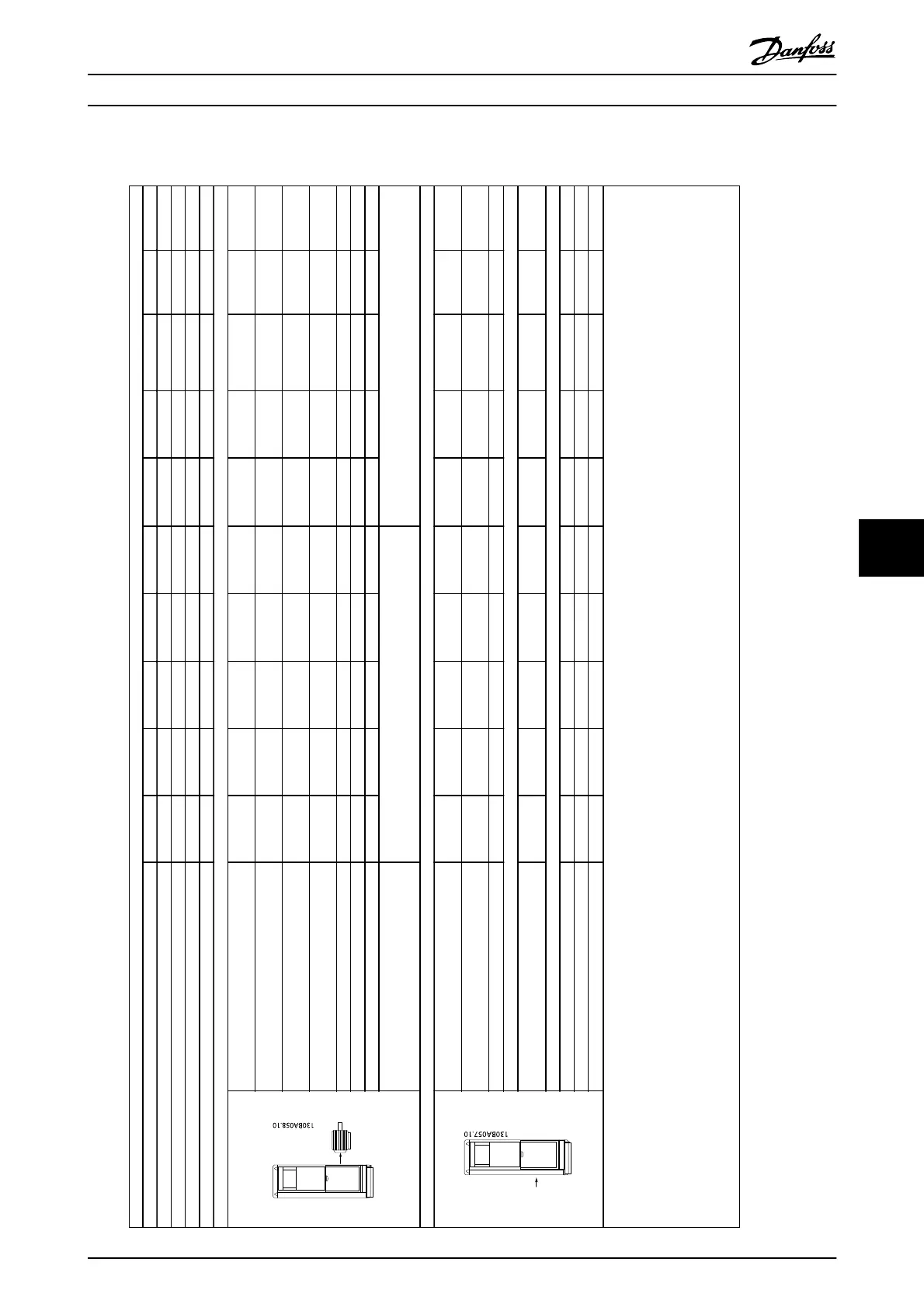
8.1.1 Mains Supply 3x525-690 V AC
Normal overload 110% for 1 minute
Size: P11K P15K P18K P22K P30K P37K P45K P55K P75K P90K
Typical Shaft Output [kW] 11 15 18.5 22 30 37 45 55 75 90
Typical Shaft Output [HP] at 575 V 10 16.4 20.1 24 33 40 50 60 75 100
IP21/NEMA 1 B2B2B2B2B2C2C2 C2 C2C2
IP55/NEMA 12 B2 B2 B2 B2 B2 C2 C2 C2 C2 C2
Output current
Continuous
(3x525-550 V) [A]
14 19 23 28 36 43 54 65 87 105
Intermittent
(3x525-550 V) [A]
15.4 20.9 25.3 30.8 39.6 47.3 59.4 71.5 95.7 115.5
Continuous
(3x551-690 V) [A]
13 18 22 27 34 41 52 62 83 100
Intermittent
(3x551-690 V) [A]
14.3 19.8 24.2 29.7 37.4 45.1 57.2 68.2 91.3 110
Continuous kVA (550 V AC) [kVA] 13.3 18.1 21.9 26.7 34.3 41 51.4 61.9 82.9 100
Continuous kVA (575 V AC) [kVA] 12.9 17.9 21.9 26.9 33.8 40.8 51.8 61.7 82.7 99.6
Continuous kVA (690 V AC) [kVA] 15.5 21.5 26.3 32.3 40.6 49 62.1 74.1 99.2 119.5
Max. cable size
(mains, motor, brake)
[mm
2
]/[AWG]
2)
35
1/0
95
4/0
Max. input current
Continuous
(3x525-690 V) [A]
1519.52429364959 71 8799
Intermittent
(3x525-690 V) [A]
16.5 21.5 26.4 31.9 39.6 53.9 64.9 78.1 95.7 108.9
Max. pre-fuses
1)
[A]
63 63 63 63 80 100 125 160 160 160
Environment:
Estimated power loss
at rated max. load [W]
4)
201 285 335 375 430 592 720 880 1200 1440
Weight:
IP21 [kg] 27 27 27 27 27 65 65 65 65 65
IP55 [kg] 27 27 27 27 27 65 65 65 65 65
Efficiency
4)
0.98 0.98 0.98 0.98 0.98 0.98 0.98 0.98 0.98 0.98
1)
For type of fuse see
2)
American Wire Gauge
3)
Measured using 5 m screened motor cables at rated load and rated frequency
4)
The typical power loss is at normal load conditions and expected to be within +/- 15% (tolerance relates to variety in voltage and cable conditions).
Values are based on a typical motor efficiency. Lower efficiency motors will also add to the power loss in the frequency converter and vice versa.
If the switching frequency is raised from nominal the power losses may rise significantly.
LCP and typical control card power consumptions are included. Further options and customer load may add up to 30 W to the losses. (Though typically only 4 W extra for a fully loaded control card or options for slot A
or slot B, each).
Although measurements are made with state of the art equipment, some measurement inaccuracy must be allowed for (±5%).
5)
Motor and mains cable: 300MCM/150 mm
2
Table 8.7 Mains Supply 3x525-690 V AC
General Specifications and ...
VLT
®
Refrigeration Drive Design Guide
MG16G102 - VLT
®
is a registered Danfoss trademark 111
8