The natural induction causes an overshoot U
PEAK
in the
motor voltage before it stabilizes itself at a level
depending on the voltage in the intermediate circuit. The
rise time and the peak voltage U
PEAK
affect the service life
of the motor. If the peak voltage is too high, especially
motors without phase coil insulation are affected. If the
motor cable is short (a few metres), the rise time and peak
voltage are lower.
If the motor cable is long (100m), the rise time and peak
voltage increases.
In motors without phase insulation paper or other
insulation reinforcement suitable for operation with
voltage supply (such as a frequency converter), fit a sine-
wave filter on the output of the frequency converter.
To obtain approximate values for cable lengths and
voltages not mentioned below, use the following rules of
thumb:
1. Rise time increases/decreases proportionally with
cable length.
2. U
PEAK
= DC link voltage x 1.9
(DC link voltage = Mains voltage x 1.35).
3.
dU
/
dt
=
0.8 ×
U
PEAK
Risetime
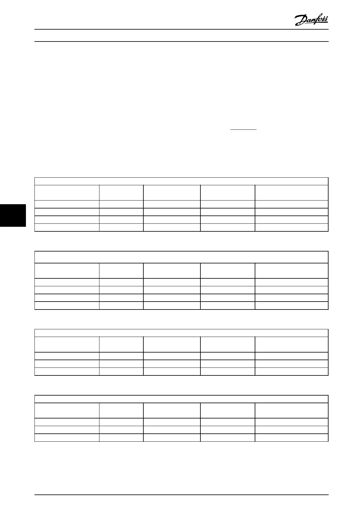
Data are measured according to IEC 60034-17.
Cable lengths are in metres.
Frequency converter, P5K5, T2
Cable
length [m]
Mains
voltage [V]
Rise time
[
μ
sec]
Vpeak
[kV]
dU/dt
[kV/
μ
sec]
36 240 0.226 0.616 2.142
50 240 0.262 0.626 1.908
100 240 0.650 0.614 0.757
150 240 0.745 0.612 0.655
Table 8.9
Frequency converter, P7K5, T2
Cable
length [m]
Mains
voltage [V]
Rise time
[
μ
sec] 011893-0001
dU/dt
[kV/
μ
sec]
5 230 0.13 0.510 3.090
50 230 0.23 0.590 2.034
100 230 0.54 0.580 0.865
150 230 0.66 0.560 0.674
Table 8.10
Frequency converter, P11K, T2
Cable
length [m]
Rise time
[
μ
sec]
Vpeak
[kV]
dU/dt
[kV/
μ
sec]
36 240 0.264 0.624 1.894
136 240 0.536 0.596 0.896
150 240 0.568 0.568 0.806
Table 8.11
Frequency converter, P15K, T2
Cable
length [m]
Mains
voltage [V]
Rise time
[
μ
sec]
Vpeak
[kV]
dU/dt
[kV/
μ
sec]
30 240 0.556 0.650 0.935
100 240 0.592 0.594 0.807
150 240 0.708 0.575 0.669
Table 8.12
General Specifications and ...
VLT
®
Refrigeration Drive Design Guide
118 MG16G102 - VLT
®
is a registered Danfoss trademark
8