Illustration 5.21
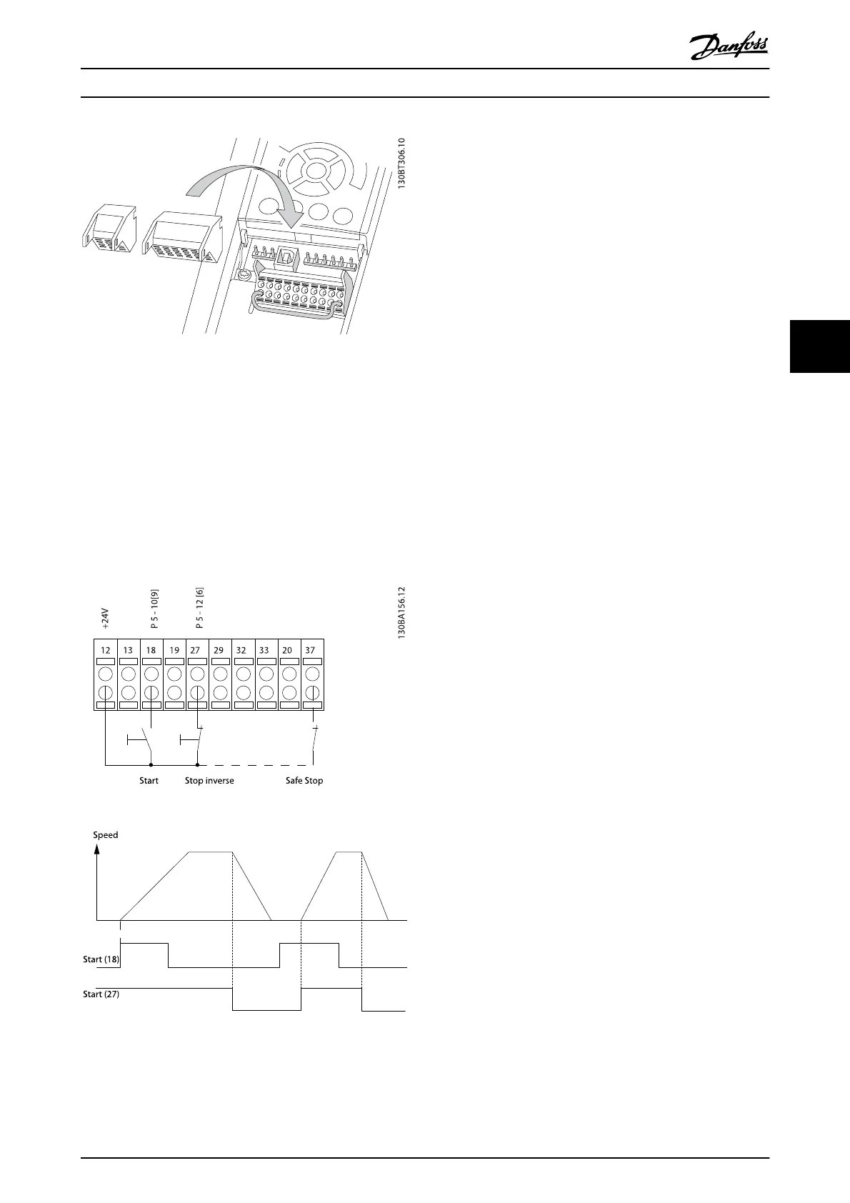
5.2.11 Basic Wiring Example
1. Mount terminals from the accessory bag to the
front of the frequency converter.
2. Connect terminals 18 and 27 to +24 V (terminal
12/13)
Default settings:
18 = start
27 = stop inverse
Illustration 5.22 Terminal 37 available with Safe Stop Function
only.
How to Install
VLT
®
Refrigeration Drive Design Guide
MG16G102 - VLT
®
is a registered Danfoss trademark 69
5