EasyManuals Logo

Danfoss VLT Design Guide

Danfoss VLT
138 pages
To Next Page IconTo Next Page
To Previous Page IconTo Previous Page
Page #75 background imageLoading...
Page #75 background image
motors. Provide further motor protection by e.g.
thermistors in each motor or individual thermal relays.
(Circuit breakers are not suitable as protection).
Illustration 5.27
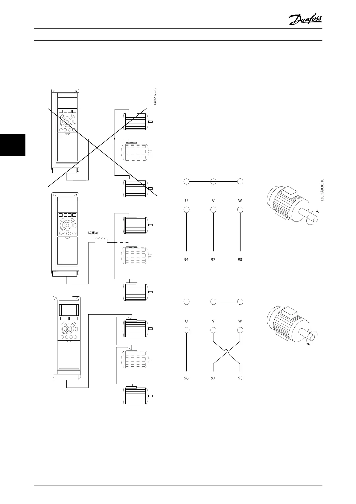
5.4.5 Direction of Motor Rotation
The default setting is clockwise rotation with the frequency
converter output connected as follows.
Terminal 96 connected to U-phase
Terminal 97 connected to V-phase
Terminal 98 connected to W-phase
The direction of motor rotation is changed by switching
two motor phases.
Motor rotation check can be performed using 1-28 Motor
Rotation Check and following the steps shown in the
display.
Illustration 5.28
5.4.6 Motor Thermal Protection
The electronic thermal relay in the frequency converter has
received the UL-approval for single motor protection,
when 1-90 Motor Thermal Protection is set for ETR Trip and
1-24 Motor Current is set to the rated motor current (see
motor name plate).
How to Install
VLT
®
Refrigeration Drive Design Guide
74 MG16G102 - VLT
®
is a registered Danfoss trademark
5
5

Table of Contents

Other manuals for Danfoss VLT

Questions and Answers:

Question and Answer IconNeed help?

Do you have a question about the Danfoss VLT and is the answer not in the manual?

Danfoss VLT Specifications

General IconGeneral
Frequency50/60 Hz
EnclosureIP20, IP21, IP55, IP66
SeriesVLT
Control TechniqueFlux Vector Control
Output Voltage0-Vinput
Control MethodFieldbus
Communication InterfacePROFIBUS, CANopen
Protection FeaturesOverload, Overvoltage, Undervoltage, Short Circuit, Ground Fault
Cooling MethodLiquid Cooled
Storage Temperature-25°C to +70°C
Relative Humidity5-95% non-condensing
AltitudeUp to 1000m (3280ft) without derating, up to 4000m (13120ft) with derating
Operating Temperature-10°C to +50°C (14°F to 122°F)

Related product manuals