VLT
®
2800 Series
Introduction to VLT
2800
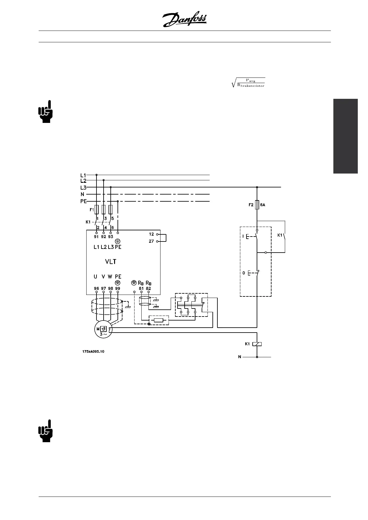
■ Protective functions during installation
When a brake resistor is installed, the best
possible endeavors should be made to avoid
overloads, as the heat generat ing from a brake
resistor may involve a fire risk.
NB!:
The brake resistor should be fitted to a
nonflammable material.
For protection of the installation, a thermal relay
should be fitted that cuts off the frequency converter
if the brake current becomes too high. Flat
pack resistors are self-protecting.
Calculate the brake current setting of the
thermal relay as follow s:
Itherm relay =
R
br
is the current brake resistor value calculated in
the section on "Calculation of b rake resistance". The
figure shows an installation w ith a thermal relay.
The brake current setting of thermal relay for Da nfoss
40% brakeresistors can be found in the table further o n.
Some of the Danfoss Brakeresistors contain a thermal
switch (see table further on). This switch is NC
(normally closed) and can be used e.g. coasting stop
reverse between terminal 12 and 27. The drive will
then coast, if the thermal switch is opened.
NB!:
The thermal s witch is not a protective
device. For protection, use a thermal
switch as shown in the figure.
MG.28.E9.02 - VLT is a registered Danfoss trademark
27
 Loading...


