VLT
®
2800 Series
■ Indicator lamps
At the bottom of the control panel are a red
alarm l amp, a yellow warning lamp and a
green voltage indicator lamp.
If certain threshold values are exceeded, the alarm
and/or warning lamp are activated, while a status
or alarm text is shown on the display.
NB!:
The voltage indicator lamp is activated when
voltage is connected to the frequency converter.
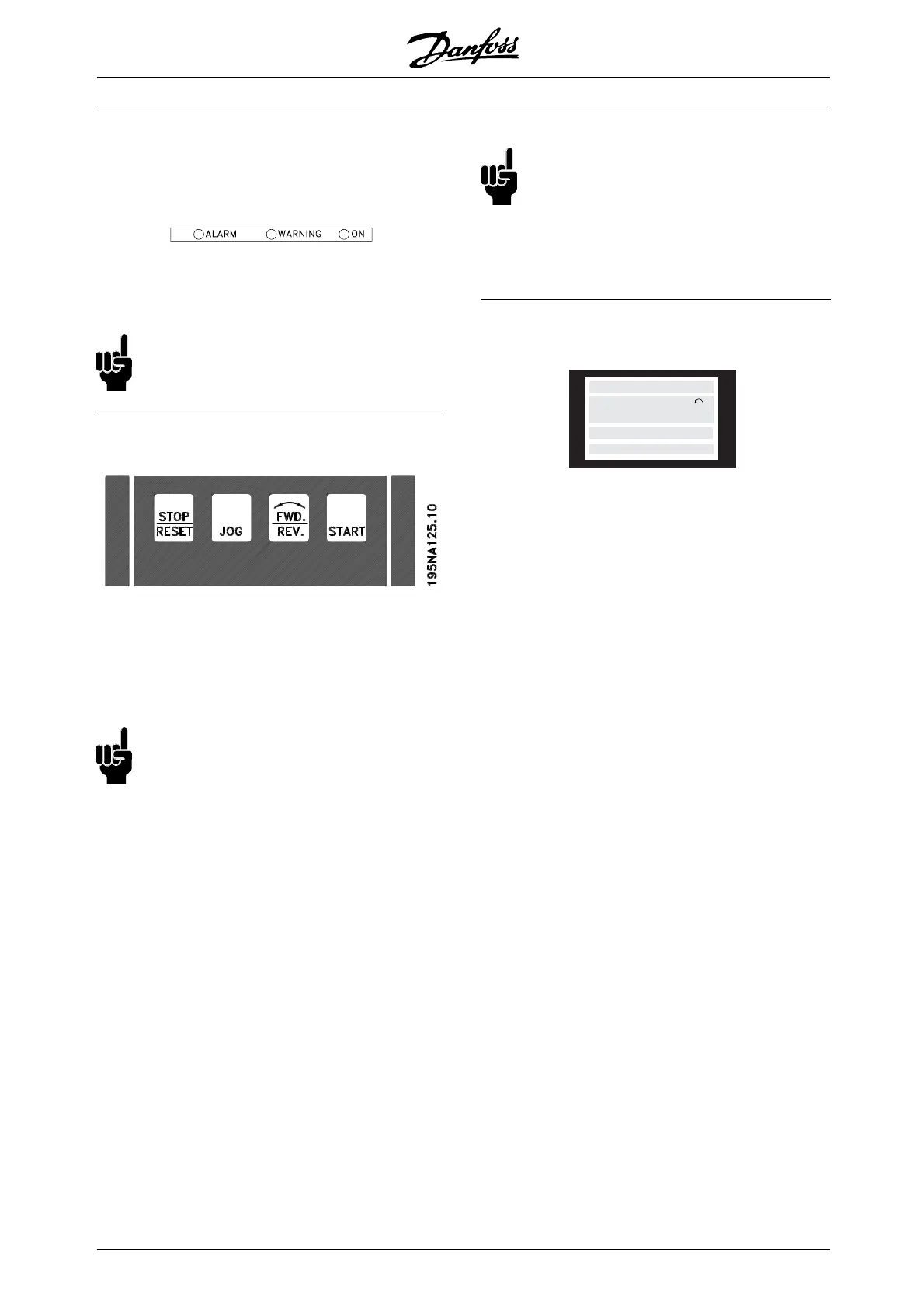
■ Local control
[STOP/RESET] is used for stopping the motor
connected or for resetting the frequency converter
after a drop-out (trip). Can be set to act ive or
inactive via parameter 014 Local stop.
If stop is activated Display line 2 will flash.
NB!:
If an external stop function is not selected and
the [STOP/RESET] key is set to inactive, the
motor c an only be stopped by disconnecting
the voltage to the motor or the frequency converter.
[JOG] changes the output frequency to a preset
frequency while the key is held down. Can be set to
active or inact ive via parameter 015 Local jog.
[FWD / REV] changes the direct ion of rotation of
the motor, which is indicated by means of the arrow
on the display. Can be set to active or inactive via
parameter 016 Local reversing.The[FWD/REV]key
is only active when p arameter 002 Local/remote
operation is set to Loca l control.
[START] is used to start the frequency converter. Is
always active, but cannot override a stop c omma nd.
NB!:
If the local control keys are set to inactive,
these will both become active when the
frequency converter is set to Local control
and Remote control via parameter 002 Local/remote
operation, with the exception of [FWD/REV], which
is only act ive in Local control.
■ Display mode
195NA113.10
VAR 2
SETUP
1
STATUS
VAR 1.1 VAR 1.2 VAR 1.3
In normal operat ion, up to 4 different display data
items can optionally be shown cont inuously: 1,1,
1,2, 1,3 and 2. The present operation status or
alarms and warnings that have been generated are
displayed in line 2 in the form of a number.
In the eve nt of alarms this is displayed in lines
3and4withexplanatorytext.
A warning will appear flashing in line 2 with
explanatory text i n line 1. The act ive Setup
will also appear on the display.
The arrow indicates the selected direction of rotation.
Here the frequency converter shows that it has
an act ive reversing signal. The body of the arrow
will disappear if a s top command is given, or if the
output freque ncy drops below 0.1 Hz.
The bottom line displays the frequency transformer’s
status. The scrollbar shows which operat ing values
can be displayed in lines 1 and 2 in Display mode.
Changes are made using the [+ / -] keys.
MG.28.E9.02 - VLT is a registered Danfoss trademark
34
 Loading...


