System design recommendations
Crankcase heater / sump heater: When the
compressor is idle, the oil temperature in the
sump of the compressor must be maintained
at no lower than 10 K above the saturation
temperature of the refrigerant on the low-
pressure side. This requirement ensures that
the liquid refrigerant is not accumulating in the
sump.
A crankcase heater is only eective if capable of
sustaining this level of temperature dierence.
Tests must be conducted to ensure that the
appropriate oil temperature is maintained under
all ambient conditions (temperature and wind).
Provide separate electrical supply for the
heaters so that they remain energized even
when the machine is out of service (eg. seasonal
shut-down).
Liquid line solenoid valve (LLSV): An LLSV
may be used to isolate the liquid charge on the
condenser side, thereby preventing against
charge transfer or excessive migration to the
compressor during o-cycles. When installed,
EXV ensures also this function. The quantity of
refrigerant on the low-pressure side of the system
can be further reduced by using a pump-down
cycle in association with the LLSV.
Pump-down cycle: A pump-down cycle
represents one of the most eective ways to
protect against the o-cycle migration of liquid
refrigerant. Once the system has reached its set
point and is about to shut o, the LLSV on the
condenser outlet closes. The compressor then
pumps the majority of the refrigerant charge into
the condenser and receiver before the system
stops on the low pressure pump-down switch.
This step reduces the amount of charge on the
low side in order to prevent o-cycle migration.
The recommended low-pressure pump-down
switch setting is 1.5 bar below the nominal
evaporating pressure. It shall not be set lower
than 2.3 bar.
Liquid receiver: Refrigerant charge optimisation
varies with compressor speed. To avoid ash
gas at low speed, a receiver may be necessary.
Receiver dimensioning requires special attention.
The receiver shall be large enough to contain part
of the system refrigerant charge, but shall not
be too large, to avoid refrigerant overcharging
during maintenance operations.
Liquid oodback during
operation
Liquid oodback occurs when liquid refrigerant
returns to the compressor when it is running.
During normal operation, refrigerant leaves
the evaporator and enters the compressor as
a superheated vapour. The suction gas can
still contain liquid refrigerant for example with
a wrong dimensioning, a wrong setting or
malfunction of the expansion device or in case
of evaporator fan failure or blocked air lters. A
continuous liquid oodback will cause oil dilution
and, in extreme situations, lead to liquid slugging.
VZH scroll compressors can tolerate occasional
liquid oodback. However system design must
be such that repeated and excessive oodback is
not possible.
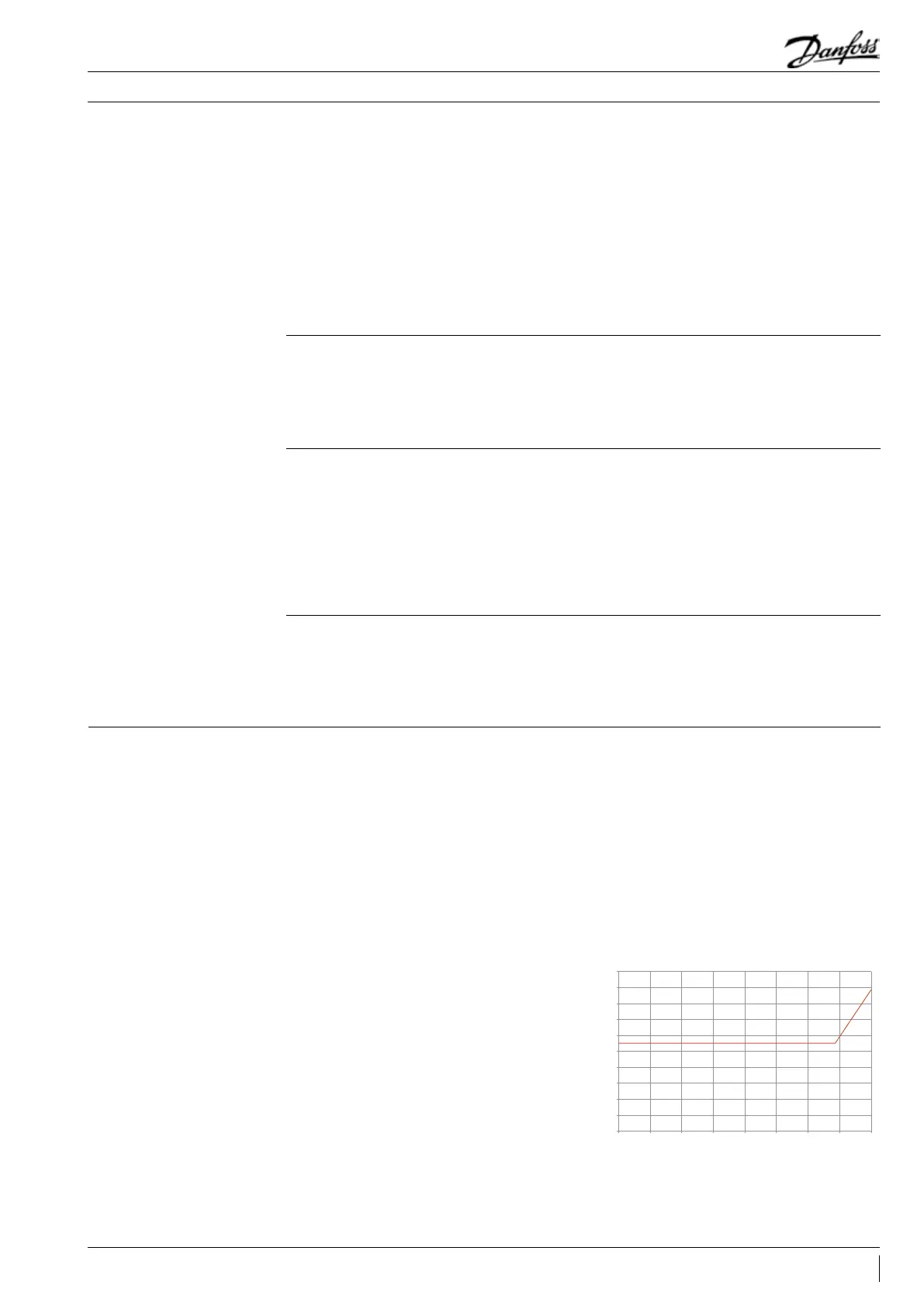
During operations, liquid oodback may be
detected by measuring either the oil sump
temperature or the discharge gas temperature. If
at any time during operations, the oil superheat
shall be above the safe limit dened in the
Dilution Chart (See graph below).
Oil superheat is given by the formula:
Oil superheat (K)= Oil sump temperature (°C) -
Saturated suction temperature(°C)
18
17
16
15
14
13
12
11
10
-25 -20 -15 -10 -5 0510 15
9
8
Unsafety Area
Safety Area
Evaporating Temperature °C
Oil Superheat (K)
49FRCC.PC.023.A8.02
Application Guidelines
 Loading...