Specic application recommendations
Suction line accumulator
Water utilizing systems
The use of a suction line accumulator is strongly
recommended in reversible-cycle applications.
This because of the possibility of a substantial
quantity of liquid refrigerant remaining in the
evaporator, which acts as a condenser during the
heating cycle.
This liquid refrigerant can then return to the
compressor, either ooding the sump with
refrigerant or as a dynamic liquid slug when
the cycle switches back to a defrost cycle or to
normal cooling operations.
The suction accumulator becomes mandatory in
case of below situations.
- Defrost test indicates there is continuous liquid
ood during defrost. More details please refer to
section “defrost test”.
- No defrost test performed.
- Sustained and repeated liquid slugging and
oodback are observed in wet climates where it
is necessary to frequently defrost the outdoor coil
in an air source heat pump.
Apart from residual moisture in the system
after commissioning, water could also enter the
refrigeration circuit during operation. Water in the
system shall always be avoided. Not only because
it can shortly lead to electrical failure, sludge in
sump and corrosion but in particular because it
can cause serious safety risks.
Common causes for water leaks are corrosion and
freezing.
Corrosion: Materials in the system shall be
compliant with water and protected against
corrosion.
Freezing: When water freezes into ice its volume
expands which can damage heat exchanger
walls and cause leaks. During o periods water
inside heat exchangers could start freezing when
ambient temperature is lower than 0°C. During
on periods ice banking could occur when the
circuit is running continuously at too low load.
Both situations should be avoided by connecting a
pressure and thermostat switch in the safety line.
Defrost cycle logic In reversible systems, the defrost logic can be
worked out to limit liquid ood back eect by:
1. Running full load during defrost to share liquid
refrigerant between all compressors.
2. Transferring liquid refrigerant from one
exchanger to the other one thanks to pressures.
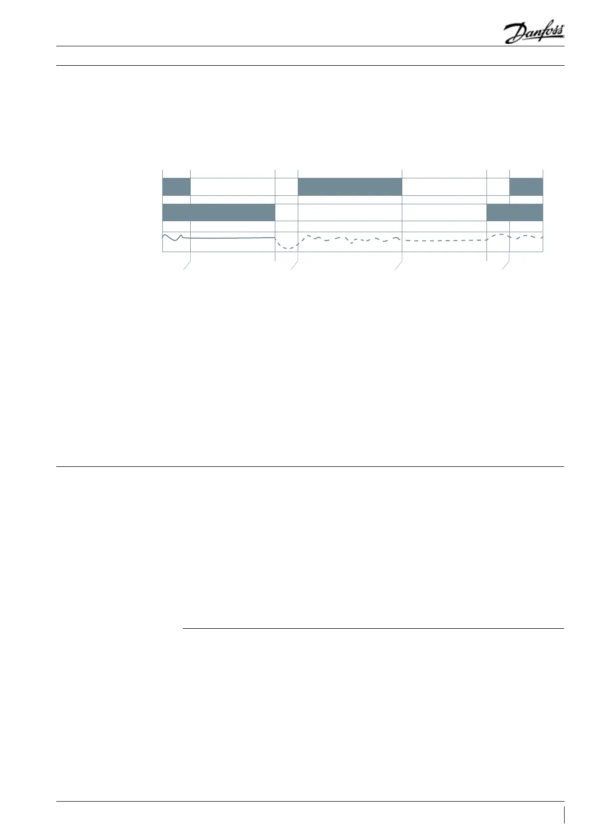
The following defrost logic combines both
advantages:
Defrost start. Stop the compressor
4 Way Valve (4WV) stays in heating mode.
EXV opened to transfer liquid from
outdoor to indoor exchanger thanks to
pressure dierence
When pressures are almost balanced,
change 4WV to cooling mode.
When pressures are almost balanced,
change 4WV to heating mode.
Start the compressor, run the
compressor at 25/30 rps for a 10
seconds period. then it is recommended
to maintain the speed at 50 rps for 10
to 15 seconds. Afterwards, go to the set
speed.
Start the compressor,and in order to
shorten the defrost period, the compressor
speed can be maintained at 70 rps during
the defrost period.
Defrost end. Stop the compressor
4 WV stays in cooling mode.
EXV opened to transfer liquid
from indoor to outdoor exchanger
thanks to pressure dierence
Defrost
Compressor
4WV
EXV
ON
Heating
100%
Defrost cycle logic must respect all system
components recommendations, in particular 4
way valve Max. Operating Pressure Dierential.
Opening degree and time have to be set in order
to keep a minimum pressure for 4 way valve
moving.
Danfoss recommend above defrost cycle logic,
but the control logic is also system specied.
53FRCC.PC.023.A8.02
Application Guidelines
 Loading...