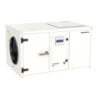
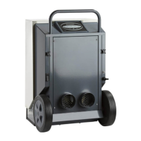
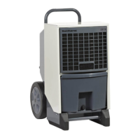
Mounting and installation instructions: Placing of CDP 85, 135, 175
Mounting and installation instructions
This section contains all necessary information for correct mounting of the dehumidier.
The electrical installation is described at the end of this section.
Introduction
CDP 85, 135, 175 can be placed in one of the following ways:
Placing of CDP 85,
135, 175
The hose from the unit to the external drainage must have at least a 2° decline.
Optimally, the drainage pipe has to be tted with a water trap to prevent air getting sucked in
through the pipe.
As an alternative, a condensate pump can be tted at the water outlet to pump the water to a
drain.
The condensate outlet is located on the air inlet side. The dehumidier is delivered with a 0.5
meter water hose, which is xed to the 3/4” connector using the clip delivered with the hose.
Make sure that the unit is mounted horizontally to ensure correct function of the condensate
outlet.
When placing the dehumidier, unimpeded access to the inspection door should be
ensured.
When the unit has been mounted, the handles are to be xed to the inspection door.
Condensate
outlet
Placement Comments
Floor The dehumidier can be placed directly on the oor.
Make sure that there is sucient space for the drain outlet and the water
trap.
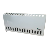
Footstands The dehumidier can be placed on shock absorbing footstands.
The footstands are available as accessories on request.
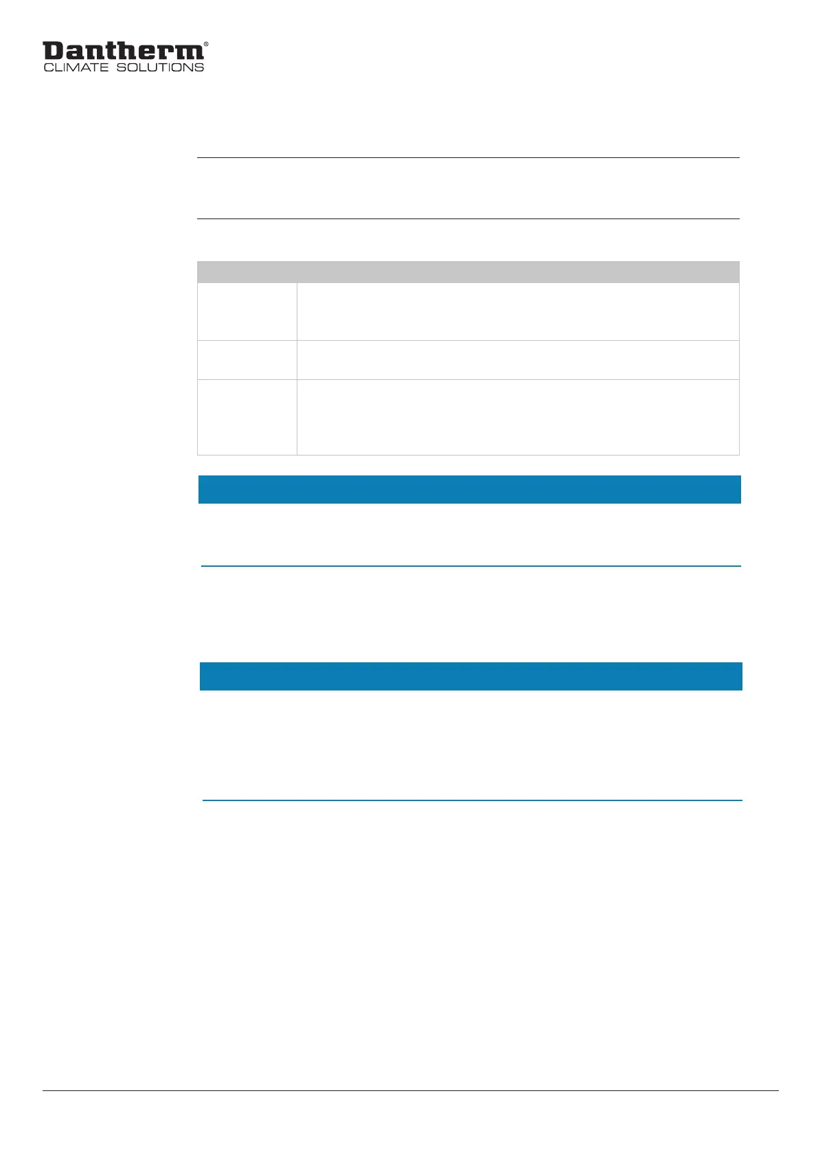
Suspension
brackets
When mounting the units onto a wall, it is recommended to t oscillation
dampers between the unit and the suspension brackets.
The suspension brackets are available as options on request , expect for the
largest unit.
NOTE
NOTE
18