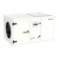
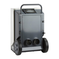
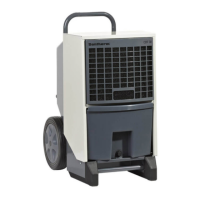
Mounting and installation instructions
Mounting and installation instructions, continued
The quantity of outdoor air should not exceed the values mentioned in the table below.
Too much outdoor air, particularly during winter, could lead to ice formation on the evaporator.
Maximum quanti-
ty of outdoor air
CDP 85 CDP 135 CDP 175
m³/h 225 375 540
The control signal for the LPHW coil control valve can be connected to X1 terminal points 5
and 6. Control output is 230V/2A.
The control valve will be switched on and o automatically depending on the heat demand.
Connection of
water heating
coils
On the air inlet side is an opening for connection of a fresh air duct. The opening is covered by
a cover, which has to be removed before connecting the fresh air duct.
If a fresh air duct is connected, we recommend that an external air exhaust fan is mounted for
drawing out the extra air in order to maintain a negative pressure dierence in the room and to
avoid moisture and chlorine-containing vapours diusing through the walls.
An external exhaust fan for maintaining the negative pressure dierence due to the introduc-
tion of outdoor air may be connected on X1 terminal points 3 and 4 on the PCB together with
the outdoor air damper. The external exhaust fan will then start along with the fresh air dam-
per. Maximum load on points 3 and 4 is 2 A.
Outdoor air duct
connection
The CDP 85, 135, 175 can be tted with low pressure hot water heating coil (LPHW). Depending
on the desired solution, an internal or external LPHW can be installed together with the unit.
The internal LPHW is designed for installation inside the unit, where as the external is a box
build duct mounted LPHW. The technical specications for the water heating coils are given in
the table in the Service section.
Water heating
coils
A water-cooled condenser may be tted allowing transfer of the excess heat from the supply
air to a water source instead of the room air.
CDP 85, 135, 175 with water-cooled condenser are supplied with coupling pipes (Ø15 mm). The
coupling pipes can be coupled together with PEX pipes by means of clamping ring ttings.
The technical specications for the water-cooled condenser are shown in the table in the Ser-
vice section.
Water-cooled
condenser con-
nection
The CDP 85, 135, 175 can be tted with electric heaters.
The electric heaters are designed for installation in the unit.
Electric heaters
Water cooling
coils
The CDP 85, 135, 175 can operate in series with an externally duct mounted low pressure
cooling water coil (LPCW). The cooling coil should be tted on the supply air side at a recom-
mended minimum distance of 1.0 meter to the previous component (eg. outlet of the dehumi-
dier).
The control signal for the LPCW coil control valve can be connected to X1 terminal points 1 and
2. Control output is 230V/2A.
The control valve will be switched on and o automatically depending on the cooling demand.
Connection of wa-
ter cooling coils
20