D-500 MK2 User Manual Firmware V-6.3
- 62 -
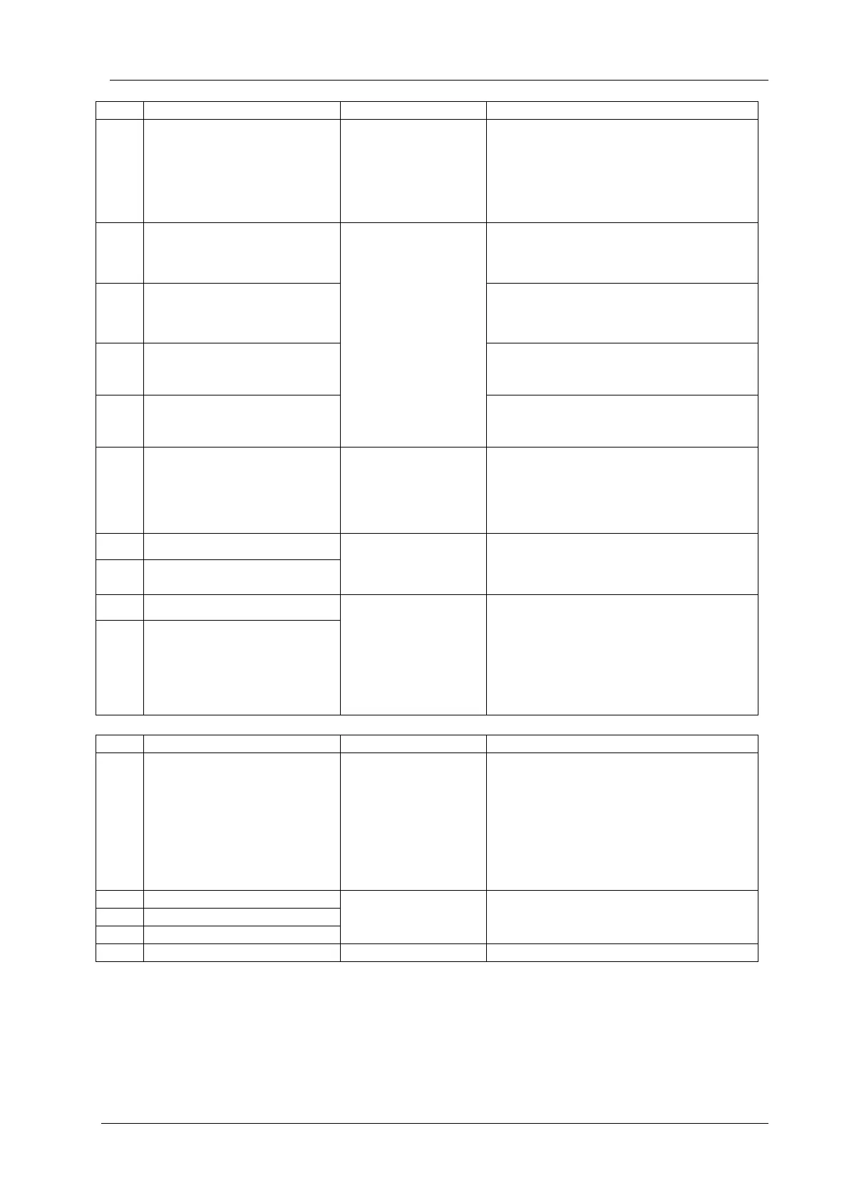
Ground potential for analog senders.
Connect to the engine body, close to
senders.
Connect to the oil pressure sender.
Do not connect the sender to other
devices.
ANALOG SENDER 1
(OIL PRESSURE SENDER)
Resistor measuring
input,
0-5000 ohms
Connect to the oil pressure sender.
Do not connect the sender to other
devices.
ANALOG SENDER 2
(COOLANT TEMP. SENDER)
Connect to the coolant temperature
sender. Do not connect the sender to
other devices.
ANALOG SENDER 3
(FUEL LEVEL SENDER)
Connect to the fuel level sender.
Do not connect the sender to other
devices.
ANALOG SENDER 4
(OIL TEMP SENDER)
Connect to the oil temperature sender.
Do not connect the sender to other
devices.
This terminal provides +5V supply for
active type senders. The maximum output
current is 50mA. An internal electronic
fuse protects the supply against overloads
or short circuits.
Analog input, 0.5 to
30V-AC
Connect the MPU unit to these inputs
Use a twisted cable pair or coaxial cable
for best results.
Digital communication
port
Connect the J1939 port of an electronic
engine to these terminals.
The 120 ohm terminating resistors are
inside the unit. Please do not connect
external resistors.
Use a twisted cable pair or coaxial cable
for best results.
This output provides energy to the
generator contactor. If the generator
phases do not have acceptable voltage or
frequency values, the generator contactor
will be de-energized. In order to provide
extra security, the normally closed contact
of the mains contactor should be serially
connected to this output.
Generator phase
inputs, 0-300V-AC
Connect the generator phases to these
inputs. The generator phase voltages
upper and lower limits are programmable.
Neutral terminal for the generator phases.
 Loading...


