D-500 MK2 User Manual Firmware V-6.3
- 61 -
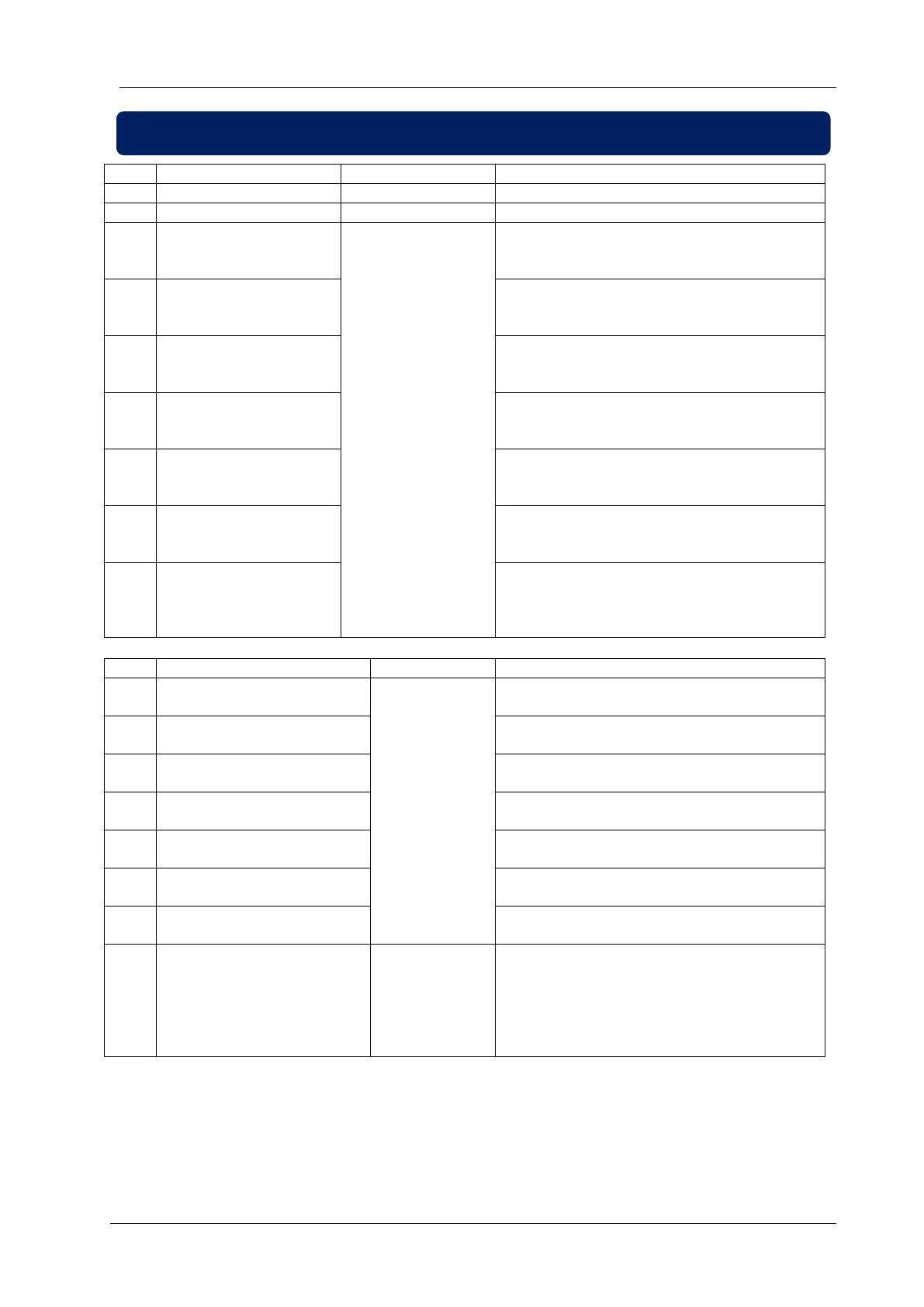
The positive terminal of the DC Supply.
Power supply negative connection.
Protected
Semiconductor
Outputs, 1A/28VDC
This relay has programmable function,
selectable from a list. Factory set as CRANK
output.
This relay has programmable function,
selectable from a list. Factory set as FUEL
output.
This relay has programmable function,
selectable from a list. Factory set as ALARM
output.
This relay has programmable function,
selectable from a list. Factory set as PREHEAT
output.
This relay has programmable function,
selectable from a list. Factory set as STOP
output.
This relay has programmable function,
selectable from a list. Factory set as IDLE
SPEED output.
Connect the charge alternator’s D+/WL terminal
to this terminal. This terminal will supply the
excitation current and measure the voltage of
the charge alternator.
The input has programmable function. Factory
set as LOW OIL PRESSURE SWITCH.
The input has programmable function. Factory
set as HIGH TEMP SWITCH.
The input has programmable function. Factory
set as EMERGENCY STOP.
The input has programmable function. Factory
set as SPARE INPUT-1.
The input has programmable function. Factory
set as SPARE INPUT-2.
The input has programmable function. Factory
set as SPARE INPUT-3.
The input has programmable function. Factory
set as SPARE INPUT-4.
AC signal driving
output and
detector input
This input is specially designed for LOW
COOLANT LEVEL detection. The terminal is
driven with a low amplitude pure sinus
waveform. It does not cause wear of the
detector electrode.