19-PIN CONNECTOR ELECTRICAL CONNECTIONS
5
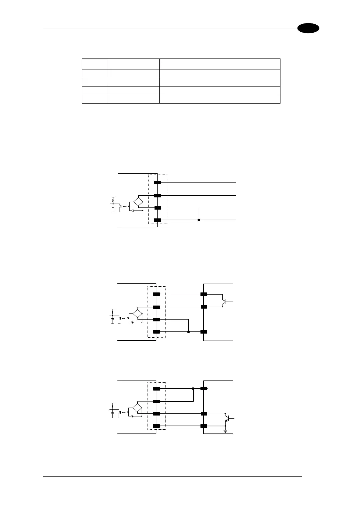
The connections are indicated in the following diagrams:
Pin Name Function
9 Vdc Power Supply input voltage +
18 I1A External Trigger A (polarity insensitive)
19 I1B External Trigger B (polarity insensitive)
25 GND Power Supply input voltage -
When current flows through the I1A-B input (External Trigger), the yellow TRIG LED (Figure
A, 6) is on.
EXTERNAL TRIGGER INPUT PNP PH-1
Vdc
GND
I1A
I1B
PNP PH-1 wires
Matrix-2000™
18
19
25
(brown) +10-30 Vdc
(black) NO
(blue) 0 V
V
CC
~
~
+
-
9
Figure 75 - External Trigger Using PNP PH-1 Photocell
EXTERNAL TRIGGER INPUT CONNECTIONS USING MATRIX-2000™ POWER
EXTERNAL TRIGGER
Matrix-2000™
18
19
9
25
Ground
V
Signal
V
CC
~
~
+
-
Vdc
GND
I1A
I1B
Figure 76 – External Trigger PNP Using Matrix-2000™ Power
EXTERNAL TRIGGER
Matrix-2000™
Signal
18
19
9
25
Ground
V
V
CC
~
~
+
-
Vdc
GND
I1A
I1B
Figure 77 - External Trigger NPN Using Matrix-2000™ Power
53