INSTALLATION
3
3.2 MECHANICAL INSTALLATION
DS4800 can be installed to operate in different positions. The four screw holes (M4 x 5) on
the body of the reader are for mechanical fixture to the L-shaped mounting bracket.
There are also three screw holes (M5 x 3) for fixture to the U-shaped mounting bracket
(Accessory).
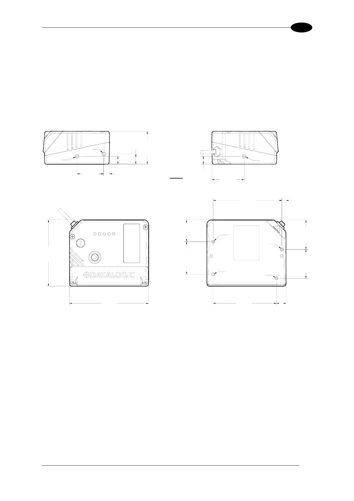
The following diagrams give the overall dimensions of the scanner and mounting brackets
and may be used for installation. Refer to par. 3.2.1 and 3.3 for correct positioning.
M4
M4
M4
M4
81
[3.19]
87.7
[3.45]
37
[1.46]
41.9
[1.65]
37.8
[1.49]
27.9
[1.10]
12.1
[0.48]
5.2
[0.21]
M5
M5
7.5
[0.30]
34
[1.34]
10
[0.39]
13
[0.51]
10
[0.39]
41.4
[1.63]
M5
101
[3.98]
42
[1.65]
85
[3.34]
mm
[in]
Figure 13 – DS4800 Overall Dimensions
27