The following diagram represents the connection between a DS6400 working as master and
a DS6400 working as a slave reader.
The cable shield for LON A/B is connected to pin1 - CHASSIS.
Figure 72 – DS6400 Master/Slave Lonworks Connection
The maximum current to be propagated to the Slave readers through the
Master is 2 A. For this reason, it is suggested to use a 24 Vdc power supply
capable of supplying up to three readers (Master + 2 Slaves).
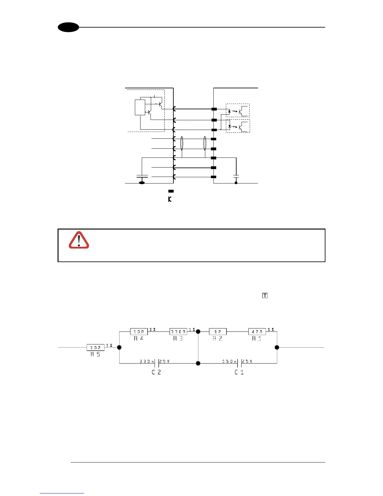
The following diagrams represent different network terminations using the BT-6000 Lonworks
terminator. In Figure 74 the BT-6000 terminator is indicated by the element, while the
figure below shows its electrical circuit in details:
Figure 73 – BT-6000 Electrical Circuit
 Loading...


