EasyManua.ls Logo

Datalogic DS6400

Datalogic DS6400
159 pages
To Next Page IconTo Next Page
To Previous Page IconTo Previous Page
Loading...
LONWORKS CONNECTIONS
57
5
The diagram below represents the termination of a DS6400 (Master/Slave model) working as
master by means of the BT-6000.
Master
BT-6000 Female Side
= male connector
= female connector
8
6
7
9
6
9
8
3
2
8
7
3
2
LON A
LON B
VS
VS_I/O
GND
T
REF_I/O
Figure 74 DS6400 Master Termination
The diagram below represents the termination of a DS6400 (Master/Slave model) working as
slave by means of the BT-6000 terminator.
Slave
BT-6000 Male Side
8
7
8
7
LON A
LON B
T
= male connector
= female connector
Figure 75 DS6400 Slave Termination
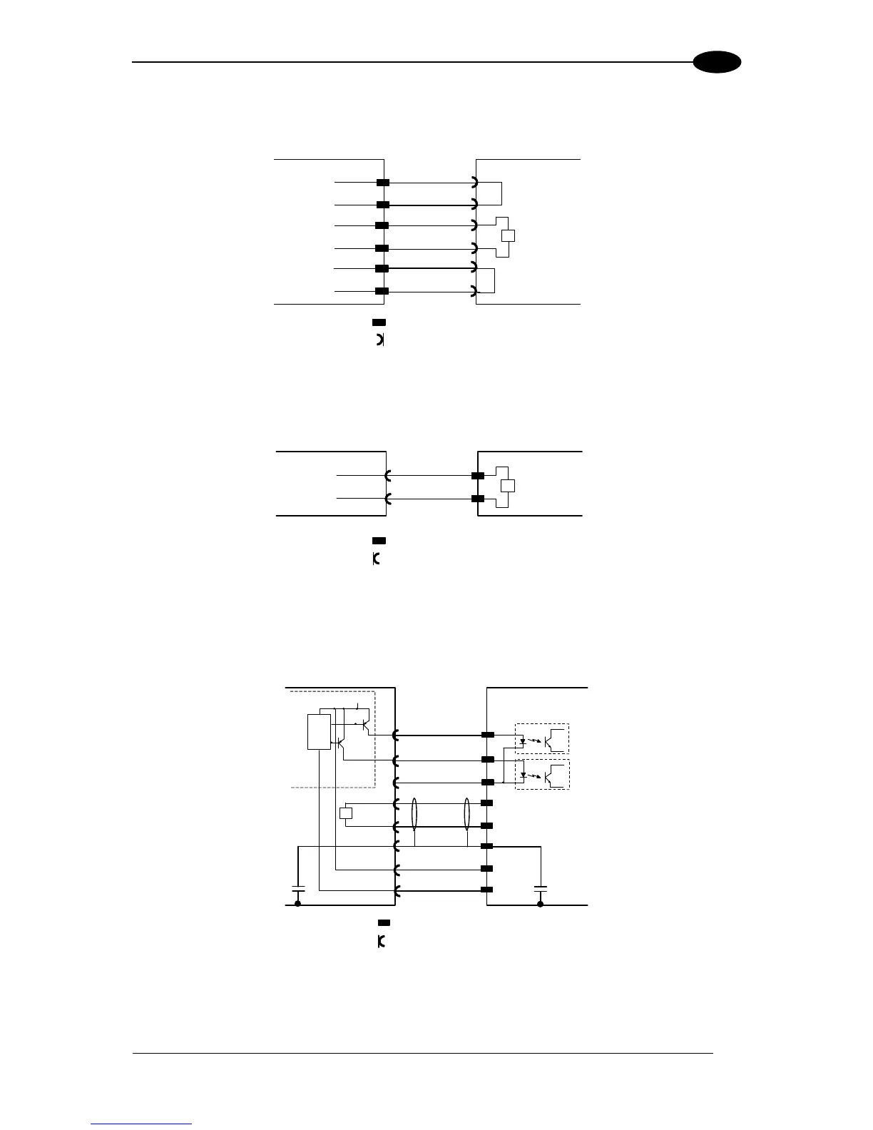
The diagram below represents the connection between a DS6400 Fieldbus model, which
always works as master, and a Master/Slave model working as a slave reader.
Fieldbus Master
8
Slave
3
7
5
4
3
5
4
VS_I/O
REF_I/O
9
1
2
8
7
9
1
2
LON A
LON B
VS
GND
AWG 16
AWG 16
T
= male connector
= female connector
CHASSIS
CHASSIS
Figure 76 DS6400 Fieldbus Master to Slave Lonworks Connection
The Fieldbus master is internally terminated.

Table of Contents

Other manuals for Datalogic DS6400

Related product manuals