2-2
001-4006-101
2.3 DTE PORT INTERFACE
2.3.1 RS-232 INTERFACE SIGNAL LEVELS
DATA PORT
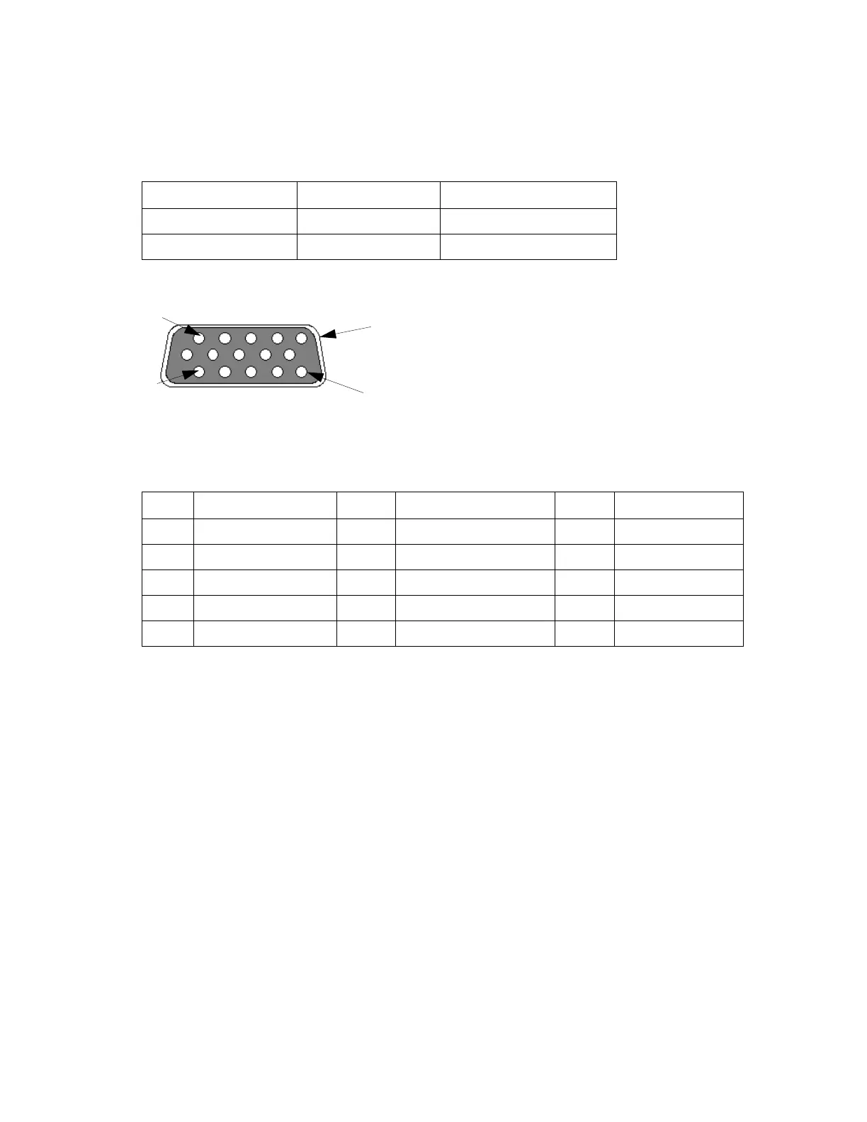
Figure 2-2 DE-15F Connector Diagram
Note: Table 2-3 is for use with the 023-3276-007 (one end unterminated) if channel selection control is
desired. If not, use 697-0000-001 cable.
Table 2-2 RS-232 Signal Levels
Term Alternates Signal level
ON asserted, spacing +3 to +15 V
OFF dropped, marking -3 to -15 V
Table 2-3 Data Port Connector Pinout
Pin Name Pin Name Pin Name
1 Ground 6 Ground 11 CS 0
2 Rx Data 7 CTS 12 CS 1
3 Tx Data 8 RTS 13 CS 2
4 Test Audio 9 DCD 14 RSSI
5 B+ Power 10 B+ Power 15 DTR_PGM
11
1
15
5