2-4
001-4006-101
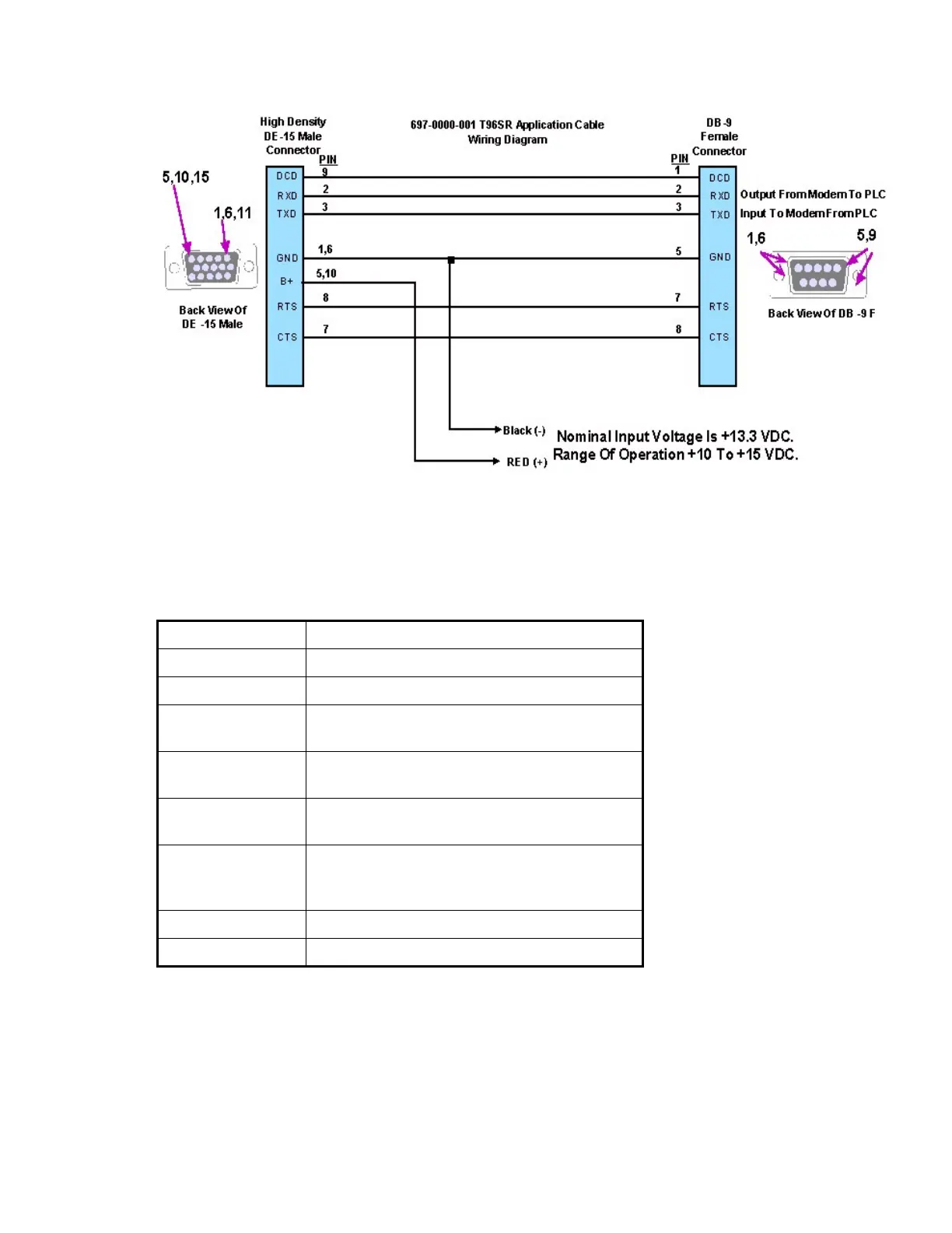
Figure 2-4 DE-15 - DB-9 Terminated Cable Assembly Accessory
2.3.3 INTERFACE SIGNAL DESCRIPTION
In the table, “gnd” indicates that the pin should be connected to ground (pin 1 or 6)
Table 2-4 Signal Description
B+ Power (input) 10 - 16 VDC (13.3V nominal) maximum 2.5A
Rx Data Received Data from T-96SR to DTE
Tx Data Transmit Data from DTE to T-96SR
CTS Clear to Send. Asserted when the T-96SR is ready to
accept Tx data
RTS Request to Send. Causes the T-96SR to transmit
when asserted by the DTE.
DCD Data Carrier Detect. Asserted by the T-96SR when a
data signal is being received
DTR Data Terminal Ready. Asserted by the Field
Programming Software to select setup mode. Do not
connect to this pin for user applications.
Test Audio Output signal used during adjustment and testing
RSSI Output signal used during testing