ALIGNMENT PROCEDURE
34
SH4 BASE-STANDARD
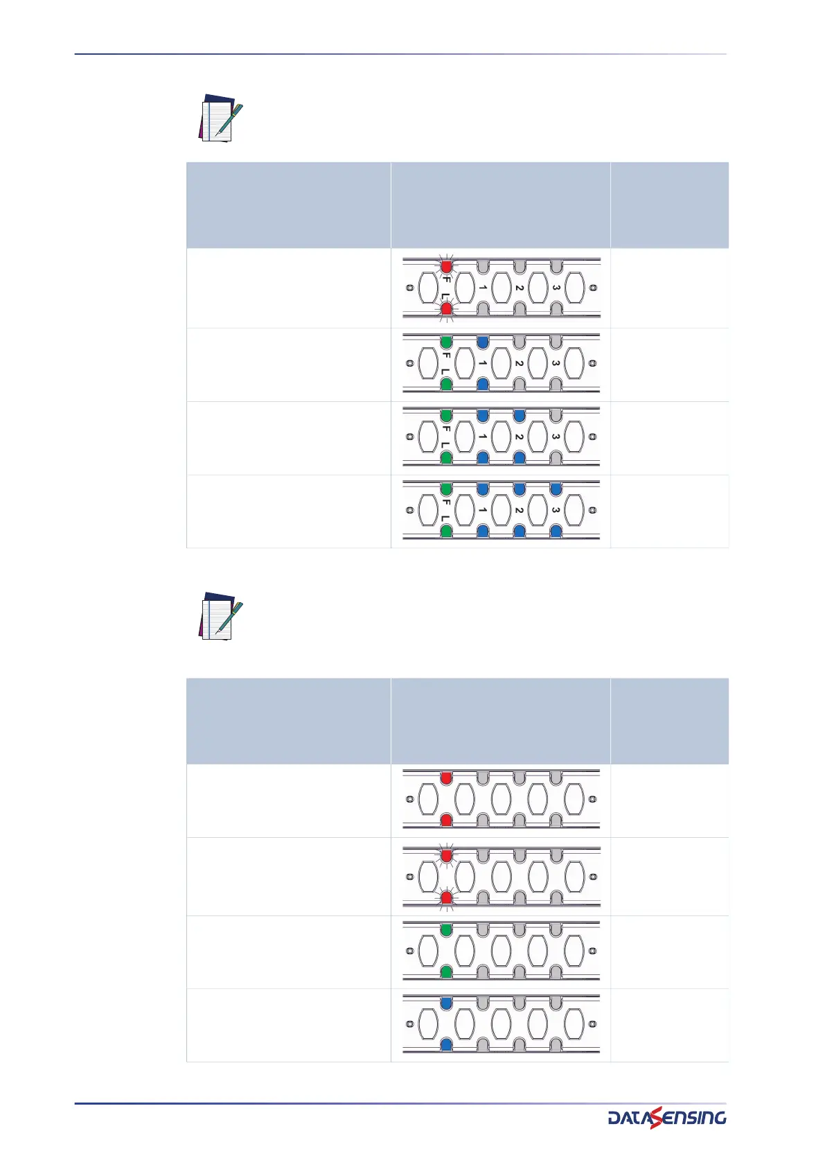
Table 2: Alignment signaling in normal operation
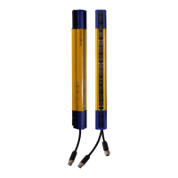
Table 3: Single module alignment signaling
NOTE: In normal operation signal level is reported by the same LEDs used
in alignment mode but the F/L LED will lit Green/Red depending on the sta-
tus of optics on the second module.
INDICATION LED CONFIGURATION
OSSD STATUS
RESULT IN
NORMAL
OPERATION
At least one beam intercepted on
second module
OFF
Minimum Signal Level
(weaker beam analog level <2.5V)
ON
Medium Signal Level
(weaker beam analog level <3V)
ON
Maximum Signal Level
(weaker beam analog level >3V)
ON
NOTE: On SH4 light curtains each optical module but the first (15 cm seg-
ment for 14/30 mm resolution) will signal the status of its optics both in
normal operation and alignment mode through a RGB module status LED.
Modules with intercepted beams will blink red.
INDICATION LED CONFIGURATION
OSSD STATUS
RESULT IN
NORMAL
OPERATION
At least one beam of other
modules intercepted
OFF
At least one beam of module
intercepted
OFF
All beams of module free with
good signal
ON
At least one beam of module with
minimum signal
ON