CASCADE SYSTEM
84
SH4 BASE-STANDARD
CONNECTION
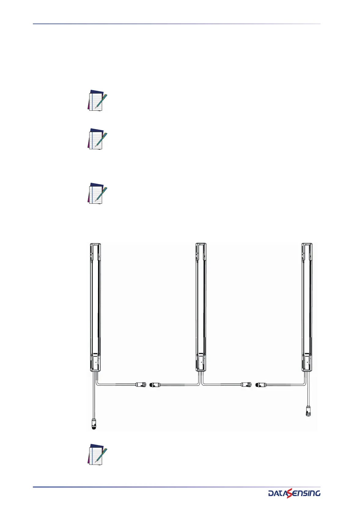
In order to connect SH4 units in a cascade system, follow the steps below:
1. Connect the M12-5 poles female connector of the MASTER unit to the M12-5
poles male connector of following slave unit.
2. Same way a LAST SLAVE can be connected to the MID SLAVE.
RX connection
NOTE: When the distance between units doesn't allow a direct connection
an optional M12 male to M12 female 5 pole cable may be used up to 10 m
cable length. Refer to Accessories appendix to see the available models.
NOTE: When using a SH4-XX-XXXX-C-5-5 model as LAST SLAVE the M12
female connector will provide muting inputs with same pinout of MASTER
unit (depending on the configuration for advanced models). For more
details please refer to SH4-XX-XXXX-SM-8-5 or SH4-XX-XXXX-A-12-5
connections on the respective Product Reference Guide.
NOTE: When using an SH4-XX-XXXX-A-12-5 model as MASTER unit, pin 11
(GP_IO2) from 12 poles male connector must be left floating.
NOTE: See chapter “Connections” for consult the connector’s pin-out.
M12 8 or 12 pin, male
M12 5 pin
female
M12 5 pin
male
M12 5 pin
female
M12 5 pin
male
M12 5 pin female or none