15
2a
2a
C.1
1a
1
2 / 2a
3 / 3a
C
M7
Moving position
Moving position
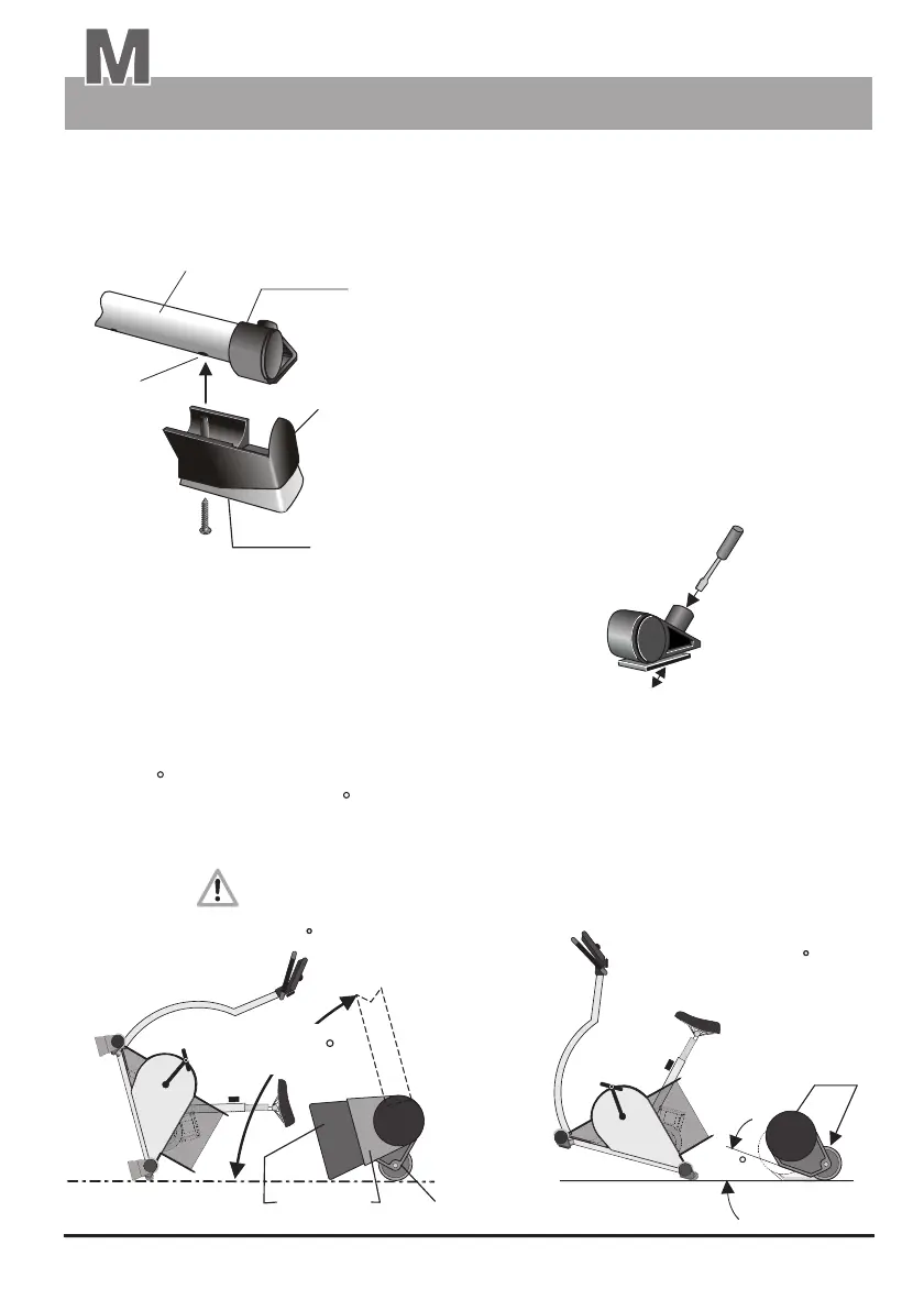
The rear standard feet (2a) are equipped with roller casters to ease moving the ergometer. When the
swing feet are installed, (left SF/right SF) the device must be raised to a relatively steep angle
(approx. 75 /Fig. D) to bring the roller casters in contact with the floor. Without swing feet raising
the frame to an angle of approx. 15 (Fig. D.1) is enough.
(without "Swing feet")
(with "swing feet")
D
D.1
The swing feet (right SF and left SF/Fig. C) are attached to
the feet from underneath. The pins of the plastic feet (3/3a)
must engage in the corresponding holes (1a) of the support
feet (1) below the standard feet (2/2a). The adjusting pin of
the front standard feet should be completely screwed in.
Otherwise, the swing feet cannot snap into place.
ergo_bike swing effect feet / Assembly
The swing feet can be removed by simply pulling them out
or by giving them a sharp rap, provided they are only
snapped in position.
When using the ergo_bike without the swing feet
on an uneven floor, use a screw driver to adjust
the pin of the front standard feet (see fig C.1) to
achieve an even stand.
left SF /
right SF
"swing feet"
Screw
It is possible to attache the swing feet with screws
(approx. 4.5x30mm) to improve the stability.
Frame
(lifted to approx. 15 )
Frame
(lifted to approx. 75 )
"swing feet"
front
foot
with floor
level adjustment
Assembly
Description
approx. 75