6
Sect/Secc 1
DriveRack
™
Control Bus LED
This LED (when lit), indicates that the 481 is connected to the control bus.
When it is flashing, the 481 is sending/receiving network information.
Remote LED
This LED (when lit), indicates that the 481 is connected to the 480R. When
it is flashing, the 481 is sending/receiving information from the 480R.
PC LED
This LED (when lit), indicates that the 481 is connected to the PC. When
it is flashing, the 481 is sending/receiving information from the PC.
Input Meters
The 481 DriveRack™ provides the user with four independent 6-segment
lightpipe™ input meters that range from -30 to +22 dBu. Note: These
meters are calibrated for the +22dBu setting of the gain jumpers.
Output Meters
The 481 DriveRack™ provides the user with eight independent 6-segment
lightpipe™ output meters that range from -30 to +22 dBu. Note: These
meters are calibrated for the +22dBu setting of the gain jumpers.
Power Switch
Turns the 481 DriveRack™ on and off. Note: dbx Professional Products
recommends that power amps connected to the DriveRack™ should be
powered down prior to cycling the DriveRack™
.
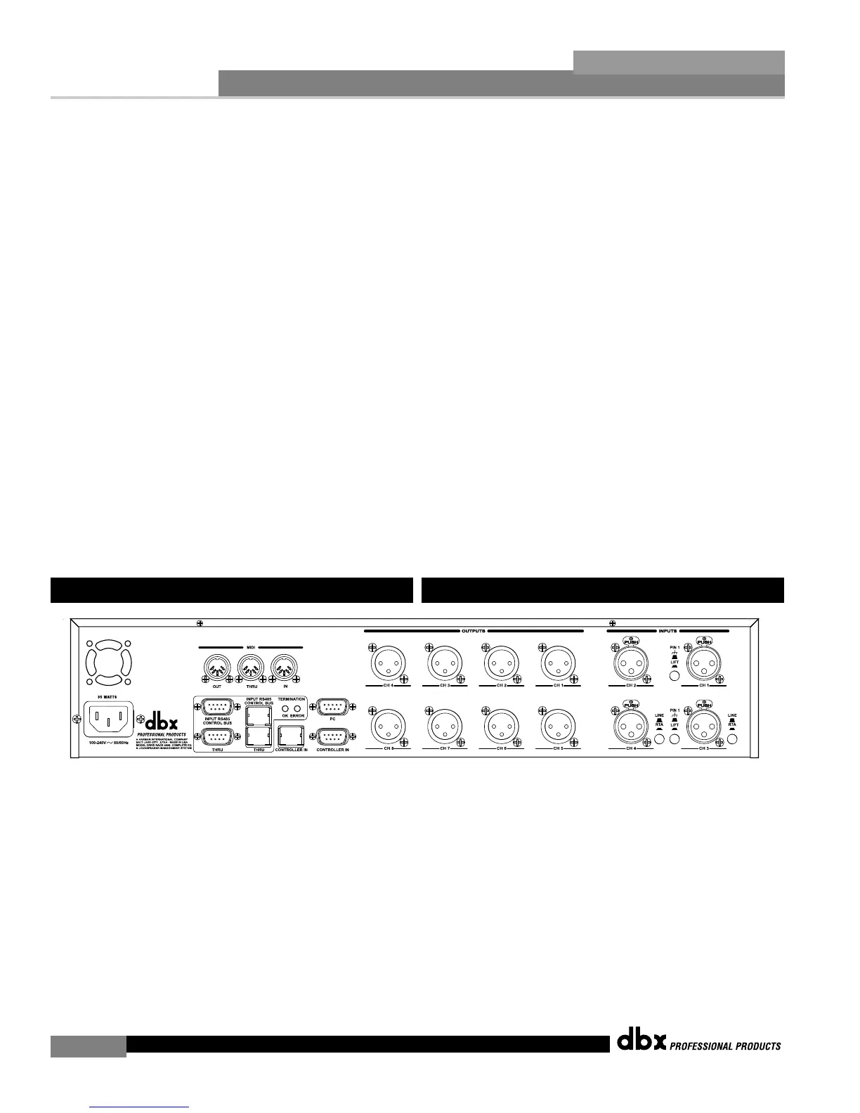
IEC Power Cord Receptacle
The 482 comes with an International power supply that will accept
voltages ranging from 100V-240V at frequencies from 50Hz-60Hz. An IEC
cord is included.
MIDI In, Out and Thru Connectors
These connectors provide MIDI functionality to the 482 DriveRack™. The
In, Out and Thru jacks allow you to use the 482 DriveRack™ at any point
in the MIDI chain.
RS485 Control Bus Input (DB-9 connector type)
This input network connection is used to receive information being sent
from other units in the DriveRack™ network link.
1.5 Rear Panel Connections (482)
LED de bus de control
Este piloto (si está encendido) le indica que el 481 está conectado al bus
de control. Si parpadea, el 481 estará enviando/recibiendo información de
red.
LED remoto
Este piloto (si está encendido) le indica que el 481 está conectado al 480R.
Si parpadea, el 481 estará enviando/recibiendo información desde el 480R.
LED PC
Este piloto (si está encendido) le indica que el 481 está conectado al PC.
Si parpadea, el 481 estará enviando/recibiendo información desde el PC.
Medidores de entrada
El DriveRack™ 481 dispone de cuatro medidores de entrada Lightpipe™
de 6 segmentos independientes que oscilan entre –30 y +22 dBu. Nota:
Estos medidores están calibrados para un ajuste de +22dBu de los puentes
de ganancia.
Medidores de salida
El DriveRack™ 481 dispone de ocho medidores de entrada Lightpipe™ de
6 segmentos independientes que oscilan entre –30 y +22 dBu. Nota: Estos
medidores están calibrados para un ajuste de +22dBu de los puentes de
ganancia.
Interruptor de encendido
Enciende y apaga el DriveRack™ 481. Nota:en dbx Professional Products
le recomendamos que apague las etapas de potencia conectadas al
DriveRack™ antes de encender/apagar el DriveRack™
.
Conector de cable de alimentación IEC
El 482 viene con una fuente de alimentación Internacional que admite
voltajes comprendidos entre 100 y 240 V a frecuencias que van desde 50
hasta 60 Hz. Se incluye un cable IEC.
Conectores MIDI In, Out,Thru
Estos conectores le ofrecen funcionalidad MIDI en el DriveRack™ 482. Le
permiten conectar el DriveRack™ 482 en cualquier punto de la cadena
MIDI.
Entrada de bus de control RS485 (conector tipo DB-9)
Esta conexión de entrada de red sirve para recibir la información enviada
desde otras unidades conectadas en la red DriveRack™.
1.5 Conexiones del panel trasero (482)
DriveRack™ User Manual/Manual de instrucciones