Getting Started/Inicio
Sect/Secc 1
DriveRack
™
7
RS485 Control Thru Bus (DB-9 connector type)
This Thru network connection is used to pass information to other units in
the DriveRack™ network link.
RS485 Control Bus Input (RJ-45 connector type)
This input network connection is used to receive information being sent
from other units in the DriveRack™ network link.
RS485 Control Thru Bus (RJ-45 connector type)
This Thru network connection is used to pass information to other units in
the DriveRack™ network link.
Termination LEDs
These LEDS indicate when network is properly terminated. The Green
LED indicates that the network has been correctly terminated.
Remote Controller In Connection
This DB-9 type input connection is used to send and receive information
from the 480 Remote DriveRack™ Unit.
PC Connection
This DB-9 type connection is used to send and receive information to and
from the GUI interface.
Outputs 1-8
The output section of the 482 DriveRack™ offers eight electronically
balanced XLR connectors.
Inputs 1-4
The input section of the 482 DriveRack™ offers four electronically
balanced XLR connectors. Inputs 3 and 4 offer Line/RTA switches that
allow you to run a real time audio analyzer microphone directly into the
input of the 482 DriveRack™. The four XLR inputs of the 482 DriveRack™
also offer Pin 1 lift switches which lift the ground of the selected XLR input
pair when pressed.
Warning - For proper operation of the RTA microphone, the RTA
button must be depressed and the ground /lift switch must be in the
grounded position. When the RTA button on the back panel is depressed,
48V phantom power is applied to pins 2 and 3 of the XLR connector. To
maintain a proper ground return for the phantom power, the ground/lift
switch must be in the grounded position. This will prevent the possibility
of electrical shock.
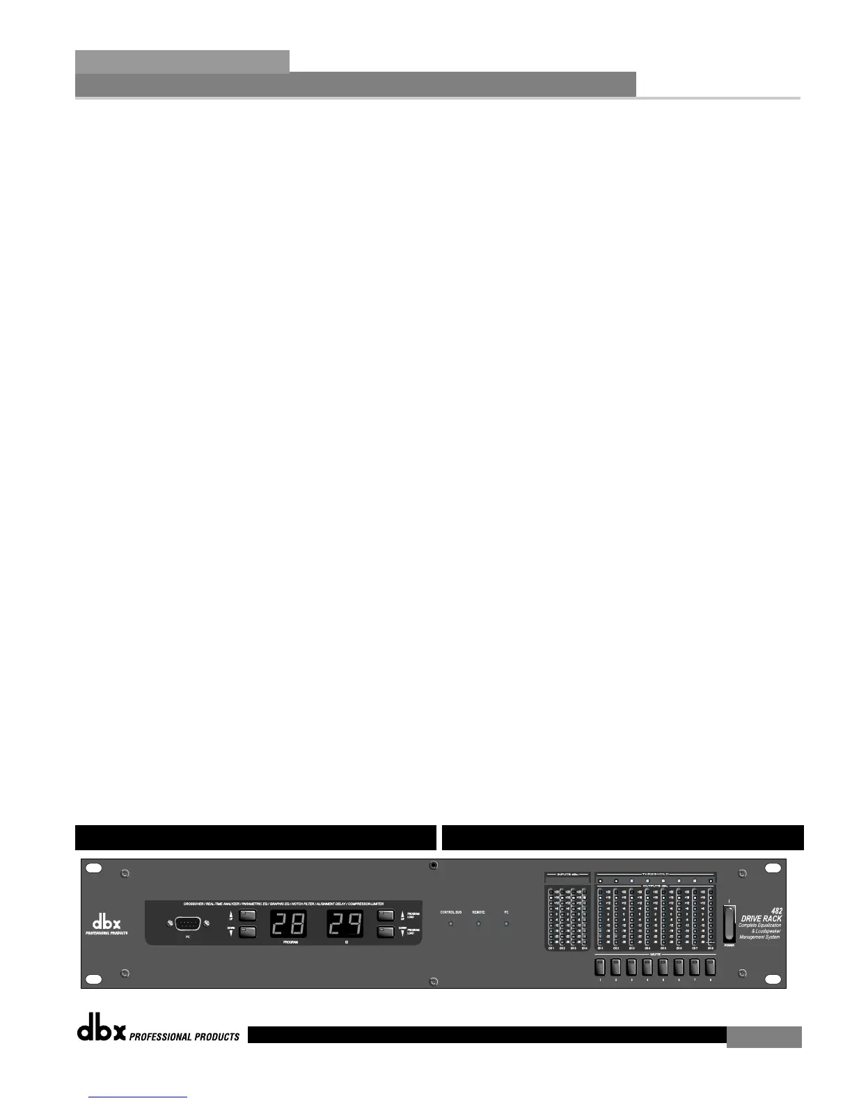
1.6 Front Panel (482)
Control de bus thru RS485 (conector tipo DB-9)
Esta conexión de red Thru se usa para enviar información a otras unidades
conectadas en la red DriveRack™..
Entrada de bus de control RS485 (conector tipo RJ-45)
Esta conexión de entrada de red sirve para recibir la información enviada
desde otras unidades conectadas en la red DriveRack™.
Control de bus thru RS485 (conector tipo RJ-45)
Esta conexión de red Thru se usa para enviar información a otras unidades
conectadas en la red DriveRack™.
LEDs de terminación
Estos pilotos le indican si una red está correctamente terminada o no.
Cuando esté encendido el LED verde la red estará terminada de modo
correcto.
Conexión de entrada de control remoto
Esta conexión de entrada de tipo DB-9 se usa para enviar y recibir
información desde la unidad de control remoto 480R.
Conexión PC
Esta conexión tipo DB-9 se usa para enviar y recibir información a y desde
la interconexión gráfica de usuario.
Salidas 1-8
La sección de salida del 482 DriveRack™ consta de ocho conectores XLR
balanceados electrónicamente.
Entradas 1-4
La sección de entrada del DriveRack™ 482 le ofrece cuatro conectores XLR
balanceados electrónicamente. Las entradas 3 y 4 disponen de
interruptores de línea/RTA que le permiten conectar un micrófono de
análisis de audio en tiempo real directamente a la entrada del DriveRack™
482. Las cuatro entradas XLR del DriveRack™ 482 también disponen de
interruptores de anulación de punta 1 que al pulsarlos desconectan la tierra
del par de entrada XLR elegido.
AVISO - Para un correcto funcionamiento del micrófono RTA, el botón
RTA debe estar pulsado y el interruptor de tierra/anulación debe estar en
la posición de tierra. Cuando el botón RTA del panel trasero esté pulsado,
se aplicarán 48V de alimentación fantasma a las puntas 2 y 3 del conector
XLR. Para mantener un retorno de tierra adecuado para la alimentación
fantasma, el interruptor tierra/anulación ha de estar en la posición de
tierra. Esto le evitará el riesgo de descargas eléctricas.
1.6 Panel delantero (482)
DriveRack™ User Manual/Manual de instrucciones