PRELIMINARY
TESTING THE COMPONENTS
Refer to page 29 for the procedure for servic-
ing the transformer.
1. Turn off the gas and disconnect power to
the cooktop.
2. Set the ohmmeter to the R x 10 scale.
3. Touch the ohmmeter test leads to the two
black primary wires. The meter should indi-
cate between 140 and 160 Ω.
4. Set the ohmmeter to the R x 100 scale.
5. Touch the ohmmeter test leads to the two
white secondary wires. The meter should
indicate approximately 6000 Ω.
Before testing any of the components, perform
the following checks:
• The most common cause for control failure is
corrosion or dirt on connectors. Therefore, dis-
connecting and reconnecting wires and con-
nectors will be necessary throughout test pro-
cedures.
• All tests/checks should be made with a VOM
or DVM having a sensitivity of 20,000 ohms-
per-volt DC, or greater.
• Check all connections before replacing com-
ponents, looking for broken or loose wires,
failed terminals, or connectors not pressed
onto terminals far enough.
• Resistance checks must be made with power
disconnected.
WARNING
Electrical Shock Hazard
Disconnect power before servicing.
Replace all parts and panels before operating.
Failure to do so can result in death or electrical shock.
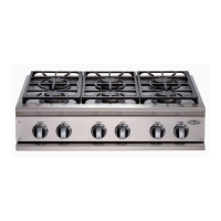
Transformer
White (Gnd)
Black
Black
Primary
Secondary
White
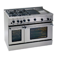
IGNITION SWITCH
Ignition Switch
Refer to page 30 for the procedure for servic-
ing an ignition switch.
1. Turn off the gas and disconnect power to
the cooktop.
2. Disconnect the wires from the switch ter-
minals.
3. Set the ohmmeter to the R x 1 scale.
4. Touch the ohmmeter test leads to the two
switch terminals. With the knob at the Off
position, the meter should indicate an open
circuit (infinite resistance).
5. Press the knob and turn the control coun-
terclockwise. The meter should indicate a
closed circuit (0 Ω).
TRANSFORMER