PRELIMINARY
23
COMPONENT ACCESS
REGULATOR MANIFOLD ASSEMBLY
1. Pull oven away from wall,making sure gas and electri-
cal supply is turned off at the valve,and gas line is dis-
connected.
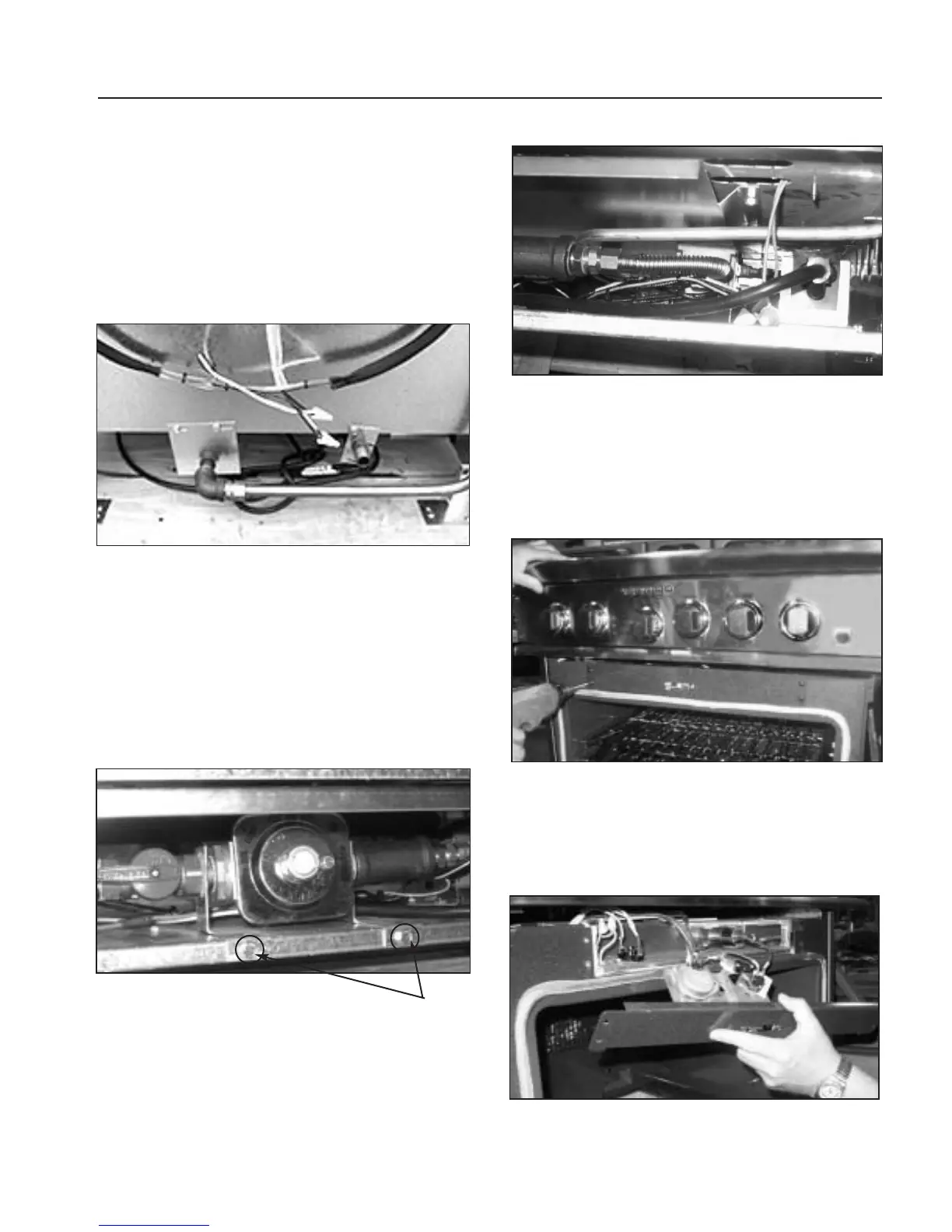
2. Loosen and remove 15/16” brass flare nut from
aluminum gas feed line at bottom,center of unit
(fig.32).
3. Remove the three (3) 5/16”bolts holding pipe brack-
ets to back of unit (fig.32).
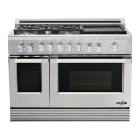
4. Remove the two (2) phillips head screws securing kick
plate. Remove kickplate (fig.23).
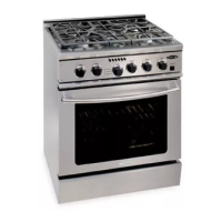
5. Remove the two (2) 5/16”bolts holding brackets on
either side of the regulator (fig.33).
6. Remove 5/8” brass flare nut at right hand side of “T”,
right side of regulator (fig.34).
7.Pulling towards you,remove regulator manifold
assembly.
MOTORIZED LATCH
1.Follow kick panel removal step (fig.23) and disconnect
power supply.
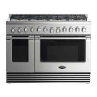
2.Remove the four (4) phillips head screws,holding latch
bracket (fig.35).
3.Remove wires from switches and motor. Remove latch
assembly.
4. Remove the four (4) screws of the access cover (fig.36).
5. Remove bracket.
Fig. 33
Bracket
Mounting
screws
Fig. 32
Fig. 34
Fig. 35
Fig. 36