PRELIMINARY
27
COMPONENT ACCESS
WARNING:
For safety reasons, it is essential that
these insulating materials are
reinstalled after servicing the unit in
exactly the same locations from which
they were removed. Failure to follow
this warning will result in failure of the
the unit to operate properly and could
result in loss of property and/or serious
injury to the user.
CONTROL PANEL REMOVAL
1. Follow kick panel removal (fig. 23) and disconnect
power supply.
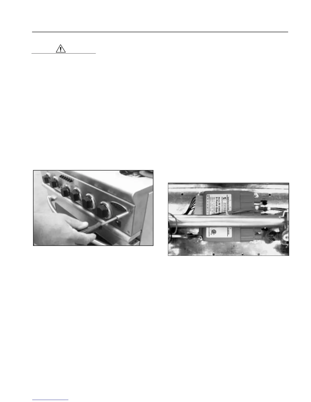
2.Remove the four (4) #15 torx head screws from control
panel (fig.54).
3.Open door to the broil stop possession and cover with
clean cloth (to protect door and control panel).
4.Remove knobs.Lay panel forward on door.
5.Disconnect wire to light switch and indicator.
SELECTION SWITCH
1. Follow kick panel removal (fig. 23) and disconnect
power supply.
2.Remove the four (4) #15 torx head screws from control
panel (fig.54).
3.Open door to the broil stop possession and cover with
clean cloth (to protect door and control panel).
4.Remove knobs.Lay panel forward on door.
5.Disconnect wire to light switch and indicator.
6.Remove selector switch mounting screws (fig.61).
7.Remove selector switch and bracket.
8.Remove wires.Note wire location on switch.
BURNER RE-IGNITER
1. Follow kick panel removal (fig. 23) and disconnect
power supply.
2.Remove the four (4) #15 torx head screws from control
panel (fig.54).
3.Open door to the broil stop possession and cover with
clean cloth (to protect door and control panel).
4.Remove knobs.Lay panel forward on door.
5.Remove the selector switch and bracket.
6.Remove the two (2) phillips screws securing the re-
igniter to the inner panel (fig.55).
7. Disconnect the Molex plug from the left side of the re-
igniter.
8. Remove the five (5) igniter “plugs”from the right side
of the re-igniter.
9.Taking care not to disturb other wires and connectors,
remove the unit from behind the manifold tube.
TOP BURNERS
1.Remove burner grates
2.See sealed burner disassembly on page 17.
Fig. 55
Fig. 54