COMPONENT ACCESS
26
PRELIMINARY
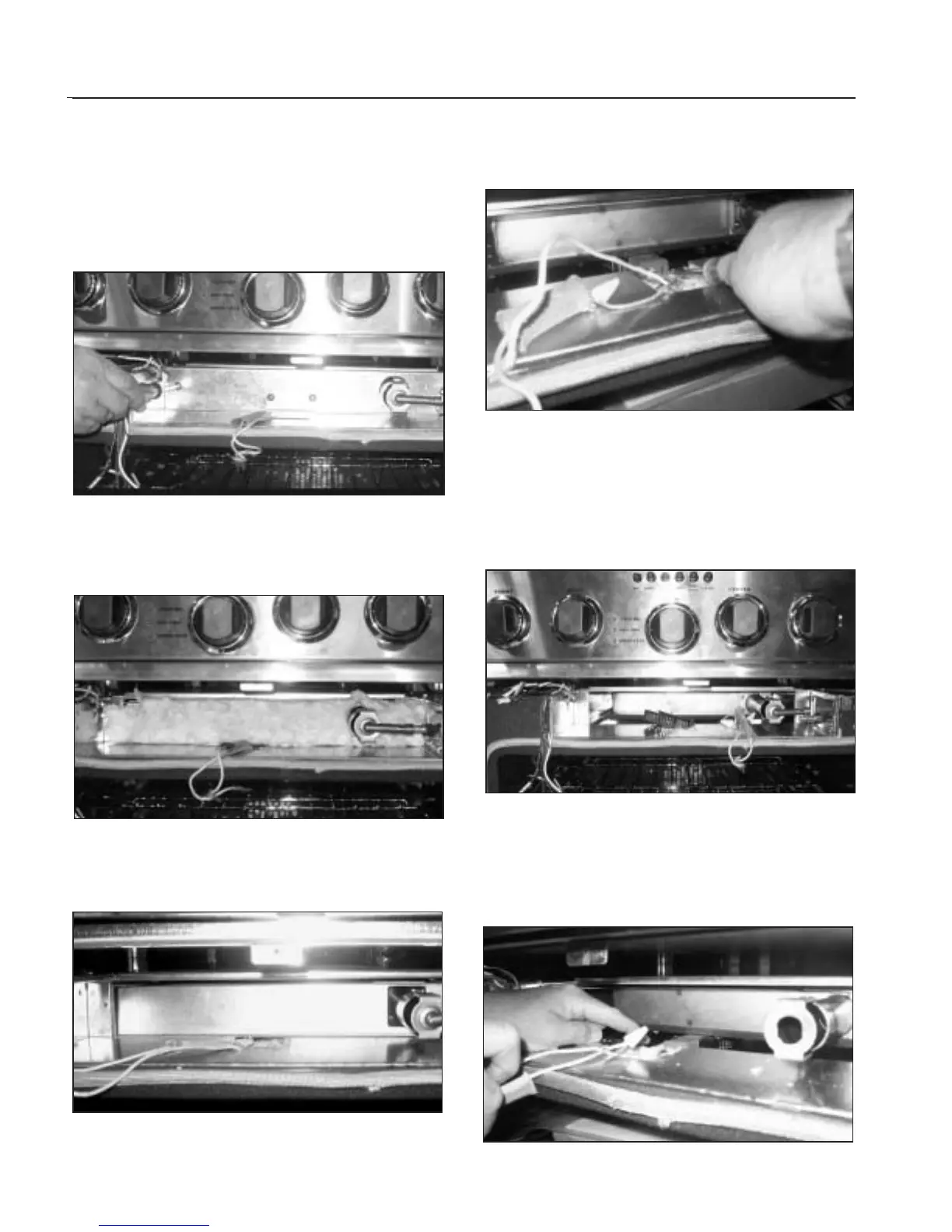
13. Remove the two phillips screws (2) securing the
center bracket to the panel.Remove the bracket by
lifting up and out.Remove the two (2) phillips screws
located on the left and right side of the panel.
Remove the panel by pulling out the left side and
sliding the right side past the broiler tube (fig.48).
14.Remove insulation from panel. Again take note of it’s
exact location for correct re-assembly (fig.49).
15.Remove the panel by pulling it straight out (There are
no screws or fasteners on this panel) (fig.50).
16. Remove the two (2) 5/16 “ hex head screws securing
the igniter assembly (fig.51).
17. Rotate the igniter assembly approximately 120
degrees counter clockwise and remove the igniter
assembly. Remove the two wire nuts from the
igniter, disconnect the wires and remove the igniter
(fig.52).
18. Grasp the broiler assembly by it’s tube and pull it
straight out of the unit. To install the new broiler
assembly or igniter reverse the dis-assembly
procedure (fig.53).
Fig. 48
Fig. 49
Fig. 50
Fig. 51
Fig. 52
Fig. 53