29
COMPONENT ACCESS
5. Remove wire guard and trim assembly from front of
unit. (fig’s 57 & 58).
6. Remove the four (4) phillips head screws from bull
nose trim assembly,two on either side (fig.59).
7. Pull thermo bulbs from oven cavity
8. Lift top up to a 45 degree angle and pull straight
towards you.
9. Remove the nine (9) 5/16”bolts,holding motor brack-
et,located on the inside of the burner box assembly
(fig.60).
10. Remove wires and remove assembly.
11. Remove the three (3) phillips head screws and two
nuts and bolts. Remove motor from bracket.
OVEN THERMOSTAT
1. Follow kick panel removal (fig. 23) and disconnect
power supply.
2.Remove the four (4) #15 torx head screws from control
panel (fig.54).
3.Open door to the broil stop possession and cover with
clean cloth (to protect door and control panel).
4.Remove knobs.Lay panel forward on door.
5.Disconnect wire to light switch and indicator.
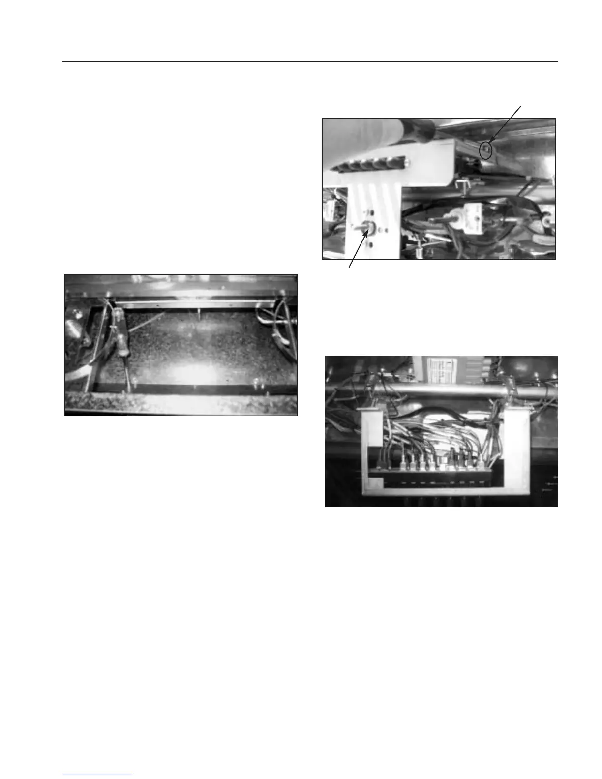
6.Remove selector switch mounting screws (fig.61).
7.Remove selector switch and bracket.
8.Remove wires.Note wire location on switch (fig.62).
9.Remove thermostat-mounting screws (fig.61).
10. Remove wire guard and trim assembly from front of
unit (fig.57 and 58).
11.Remove capillary bulb from holder inside oven cavity.
12. Feed capillary bulb up through hole in oven cavity
and back through panel (fig.63 and 64).
PRELIMINARY
Fig. 60
Fig. 61
Mounting Screw
Thermostat
Fig. 62