25
COMPONENT ACCESS
PRELIMINARY
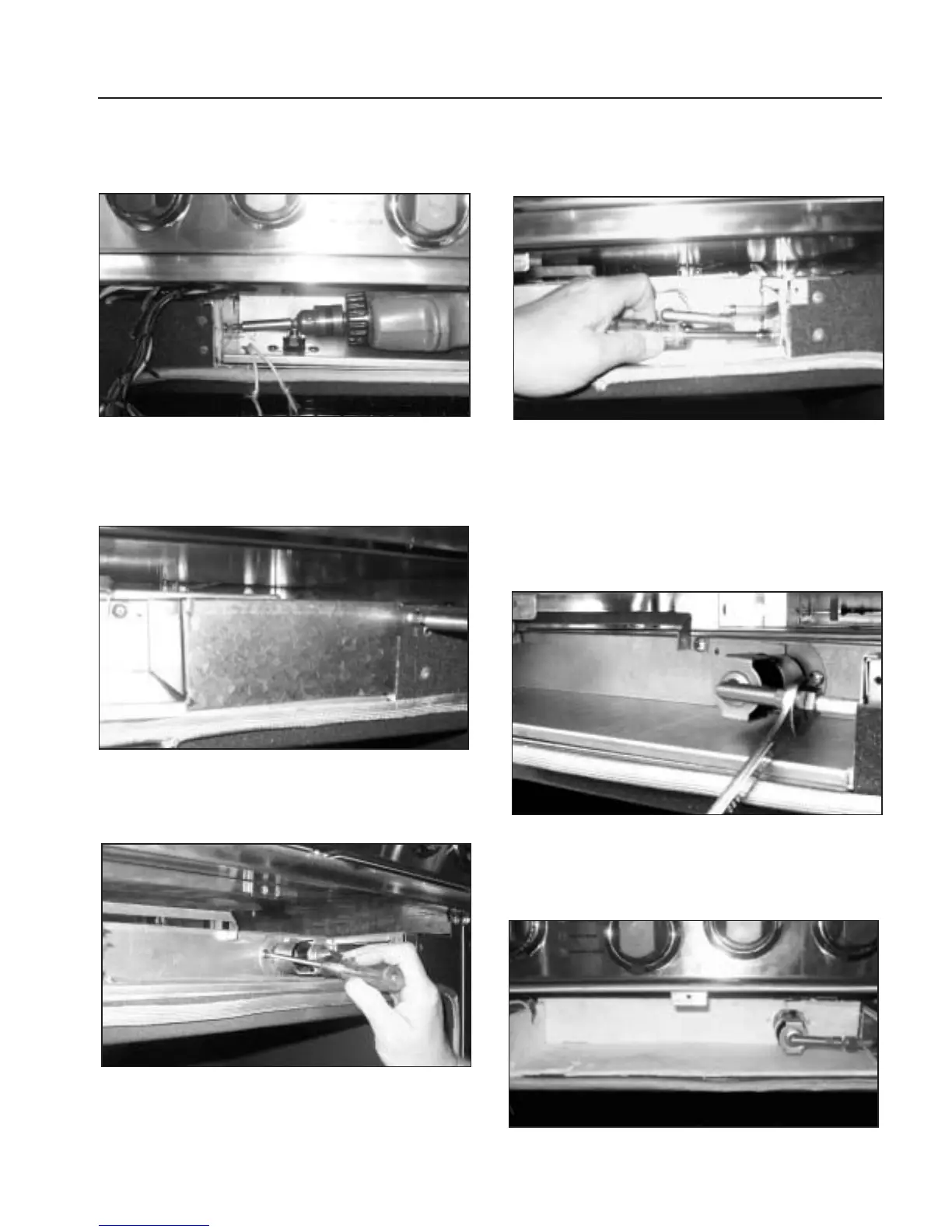
6. Remove inner panel phillips screw (1) located on the
left, front, side panel (fig.42).
7. Remove the phillips screws (2) securing the venturi
cover located on the right side of the opening.
Remove the cover (fig.43).
8.Remove the two (2) phillips screws and venturi shutters
at the base of the burner tube (fig.44).
9. Remove the 5/16”hex head screw (1) located on the
right side panel of the opening (fig.45).
10. Remove panel by tilting up and back while sliding
panel out past broiler tube assembly.
11.Disconnect the gas line fitting.Temporarily secure the
fitting nut to keep it from sliding down the tube into
the range side wall cavity (fig.46).
12. Remove insulation taking care to note the exact
location of the insulator for correct re-assembly
(fig.47).
Fig. 42
Fig. 45
Fig. 46
Fig. 43
Fig. 44
Fig. 47