DEKA DURATION DD5300
77
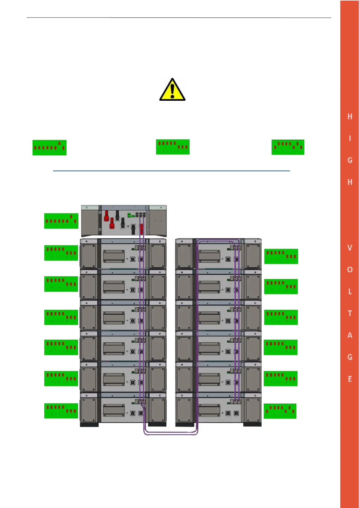
3.6.2 DATA Connections (Example of 12-Modules)
Step 1: Set up the DIP Switches as per the picture below.
Step 2: Connect the CAN and Link PORTS, starting from the HV Box PORT CAN A and LINK, then chain connection
as shown below.
The HV Box must be set up before turning it on. The DIP addresses must follow the picture below to enable the CAN
communication. The last module of the series must be terminated by addressing the module as shown in the picture to end the
CAN line.
Single HV Box Battery Module End of series
Step 3: Link all modules and the HV Box with 6 mm earthing cables (In/Out) by using the GND connections point.