DEKA DURATION DD5300
25
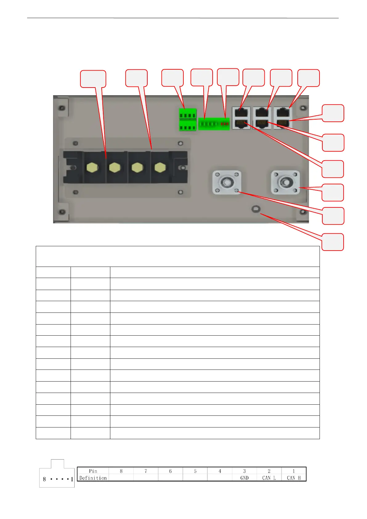
1.4 Battery Terminal Function Definition
The terminal layout is shown in the following figure:
Battery Terminal Wiring Definition Table
LOW VOLTAGE POSITIVE (+) Screw Terminal
LOW VOLTAGE NEGATIVE (-) Screw Terminal
DIP SWITCH Address HUB 5 PINS
DIP SWITCH Termination 3 PINS (120 Ohms)
LOW VOLTAGE COMMUNICATION PORT RS485
CAN – BMS to LOW VOLTAGE INVERTER
HIGH VOLTAGE SERIAL IDENTIFIER RJ45 CAN PORT
LOW VOLTAGE COMMUNICATION PORT RS485
HIGH VOLTAGE NEGATIVE (-) Fast Connector Terminal for serial connection
HIGH VOLTAGE POSITIVE (+) Fast Connector Terminal for serial connection
Attention: Interface E: RJ45 port corresponding to the CAN bus pin definition