EasyManua.ls Logo

Deka DURATION DD5300 - Power Connection Example

Deka DURATION DD5300
96 pages
Print Icon
To Next Page IconTo Next Page
To Previous Page IconTo Previous Page
Loading...
DEKA DURATION DD5300
55
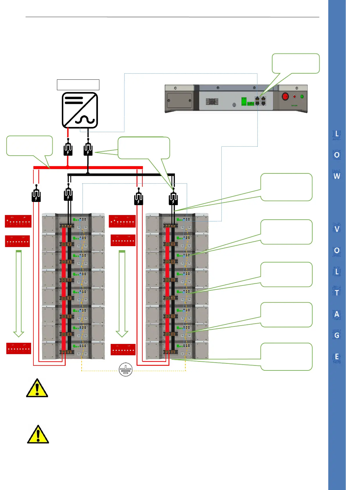
2.9.6 Power Connection Example
Communication Diagram + Power Connection
ATTENTION:
Each cluster must be equipped with an isolator to individually disconnect the battery
tower from the parallel bus bar in accordance with UL regulations.
ATTENTION:
The circuit between the inverter and the parallel bus bar must be separated by a manual switch in
accordance with UL regulations.
Master Inverter
NEGATIVE POWER
CABLES
2X50/75mm²
POSITIVE POWER
CABLES
2X50/75mm²
GROUND CABLES
10mm²
RS485 PARALLEL
RJ45 Cable
DATA COMM
GROUND CABLES
10mm²
TWO POLES
BREAKER
PARALLEL BUS
BAR
TWO POLES BREAKER
( US/UL Market)
CAN INPUT FROM
LAST CLUSTER

Table of Contents

Related product manuals