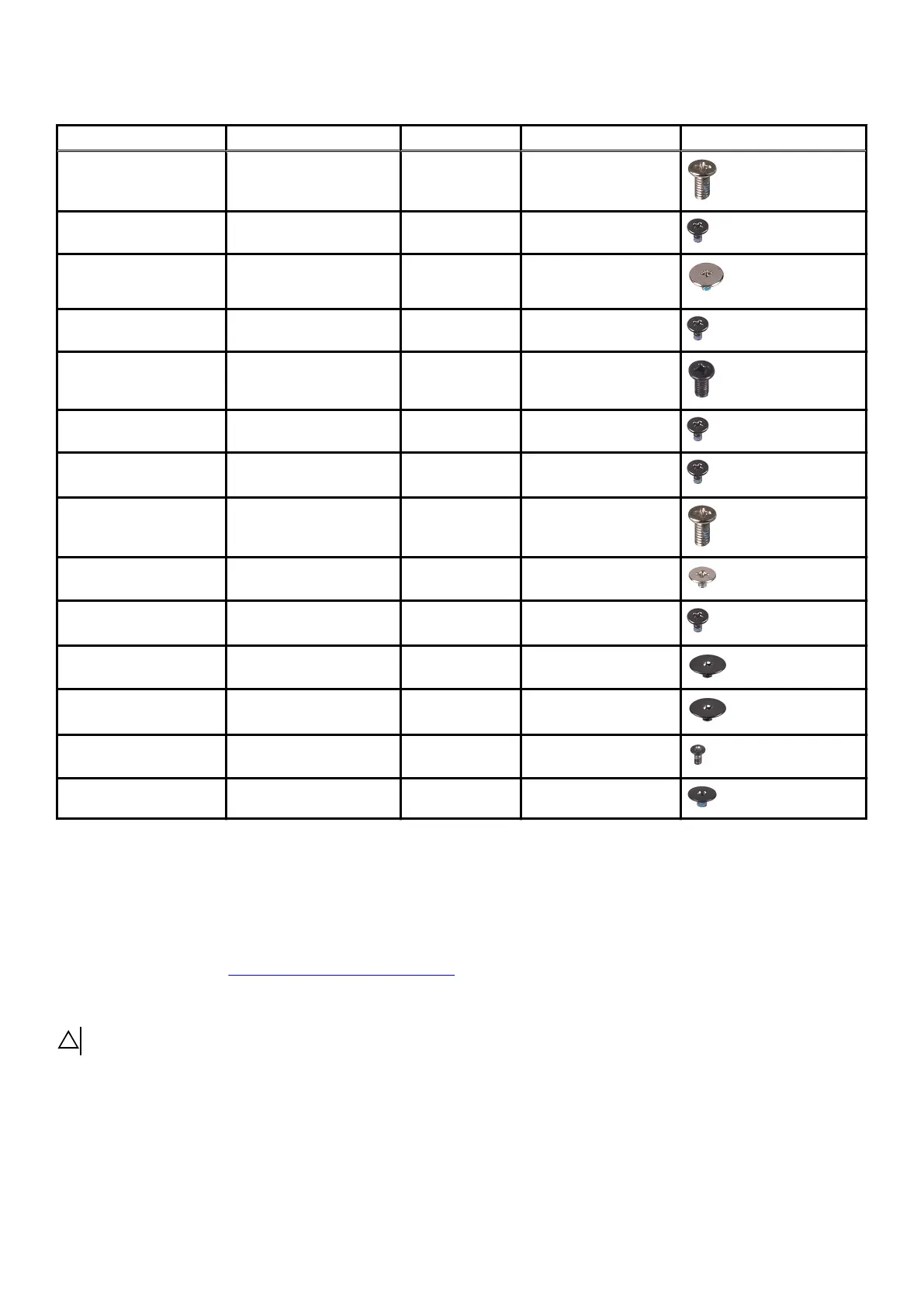
Table 1. Screw list (continued)
Component Secured to Screw type Quantity Screw image
Left I/O-board
connector
• System board
• Left I/O-board
M2x4.5 4
Left I/O-board Palm-rest assembly M2x3 3
Right I/O-board
connector
• System board
• Right I/O-board
M2x3 2
Right I/O-board Palm-rest assembly M2x3 3
Fans Palm-rest assembly M2.5x5 2
System board Palm-rest assembly M2x3 5
Fan and heat-sink
assembly
System board M2x3 10
Solid-state drive support
bracket
Palm-rest assembly M2x4.5 3
Touchpad Palm-rest assembly M2x2.5 4
Power-adapter port
bracket
Palm-rest assembly M2x3 2
Power-button assembly Palm-rest assembly M2x1.9 2
Keyboard-controller
board
Palm-rest assembly M2x1.9 2
Keyboard bracket Keyboard M1.2x2.1 10
Keyboard Palm-rest assembly M1.2x1.6 28
Base cover
Removing the base cover
Prerequisites
1. Follow the procedure in Before working inside your computer.
About this task
CAUTION: Ensure that all captive screws are loosened before prying up the base cover.
The following image indicates the location of the base cover and provides a visual representation of the removal procedure.
10