• Antenna cables
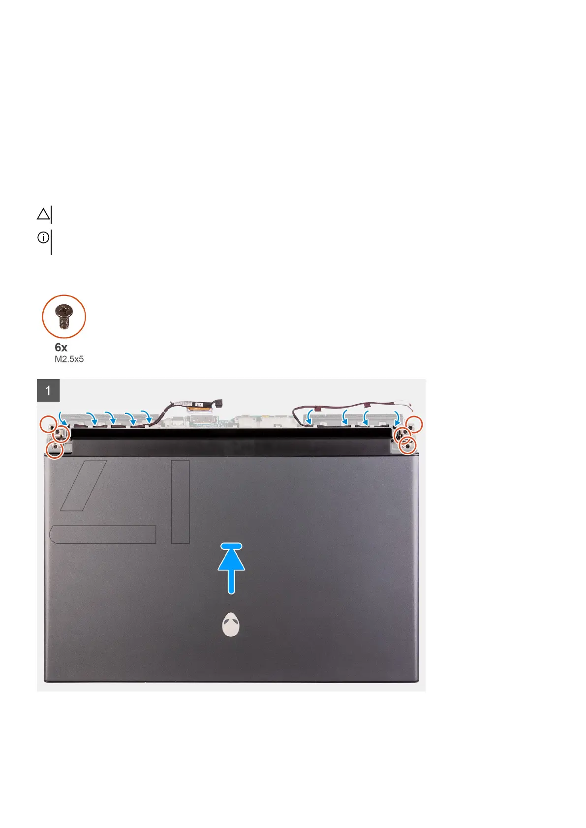
12. Remove the six screws (M2.5x5) securing the display assembly to the palm-rest assembly.
13. Gently lift the display assembly from the palm-rest assembly.
Installing the display assembly
Prerequisites
If you are replacing a component, remove the existing component before performing the installation procedure.
About this task
CAUTION: Place the computer on a soft and clean surface to avoid scratching the display.
NOTE: The display assembly is a Hinge-up Display (HUD) and cannot be further disassembled. If components within the
display assembly must be replaced, the entire display assembly is to be replaced.
The following image indicates the location of the display assembly and provides a visual representation of the installation procedure.
40