Steps
1. Adhere the Mylar into place onto the system board.
2. Push the rear I/O-cover into the palm-rest assembly snapping it into place.
NOTE: To avoid damaging your computer, ensure that the Tron light cable is not pinched and that the Mylar is pasted on
the system board before snapping the rear I/O-cover into place.
3. Replace the two screws (M2x4.5) that secure the rear I/O-cover to the palm-rest assembly.
4. Replace the two screws (M2.5x5) that secure the rear I/O-cover to the palm-rest assembly.
5. Connect the Tron light cable to the system board.
6. Route and adhere the Tron light cable into place on the system board underneath the mylar.
Next steps
1. Install the
base cover.
2. Follow the procedure in After working inside your computer.
Display assembly
Removing the display assembly
Prerequisites
1. Follow the procedure in Before working inside your computer.
2. Remove the base cover.
3. Remove the rear I/O-cover.
About this task
NOTE: The display assembly is a Hinge-up Display (HUD) and cannot be further disassembled.
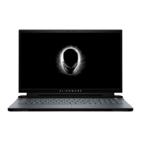
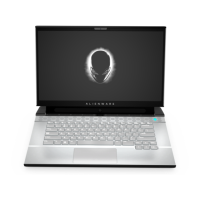
The following image indicates the location of the display assembly and provides a visual representation of the removal procedure.
37
 Loading...


