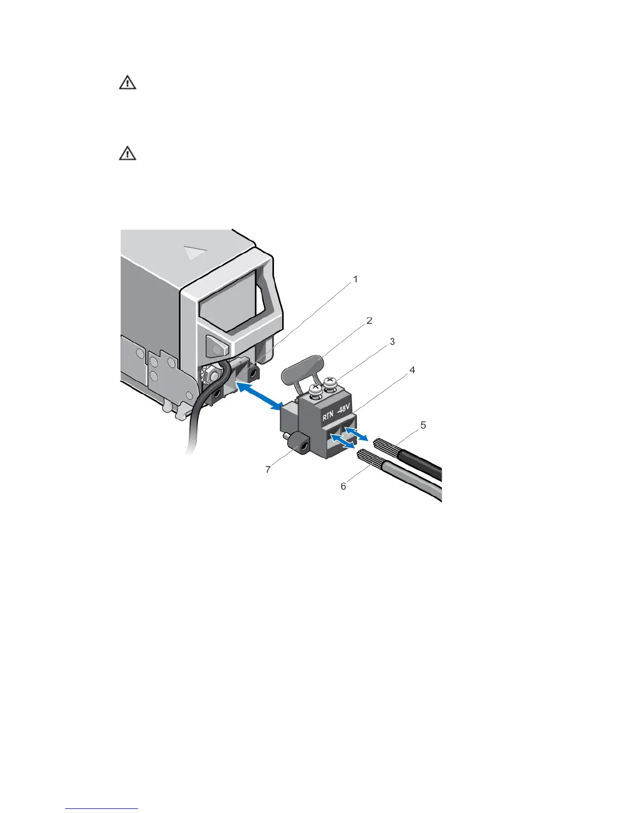
WARNING: Reversing polarity when connecting DC power wires can permanently damage the power supply
or the system.
2. Insert the copper ends into the mating connectors and tighten the captive screws at the top of the mating
connector using a #2 Phillips screwdriver. The captive screws must be torqued to 16 in lbs (1.8 N-m) to ensure
proper cable retention.
WARNING: To protect the power supply from electrostatic discharge, the captive screws must be covered
with the rubber cap before inserting the mating connector into the power supply.
3. Rotate the rubber cap to fix it over the captive screws.
4. Insert the DC power connector into the power supply.
5. Tighten the screws on the wings of the DC power connector.
Figure 41. Assembling the DC Input Power Wires
1.
DC power socket
2. rubber cap
3. captive screws (2)
4. DC power connector
5. wire –48 V
6. wire RTN
7. wings (2)
77
 Loading...