AC Power Supply Units | 27
The chassis transmits power to connected IEEE 802.3af-compliant devices through ports that are enabled
with PoE. A minimum of three power supply units (PSU) are required to enable PoE, but Dell Force10
recommends a two-plus-two redundancy configuration, so a minimum of four PSUs is recommended.
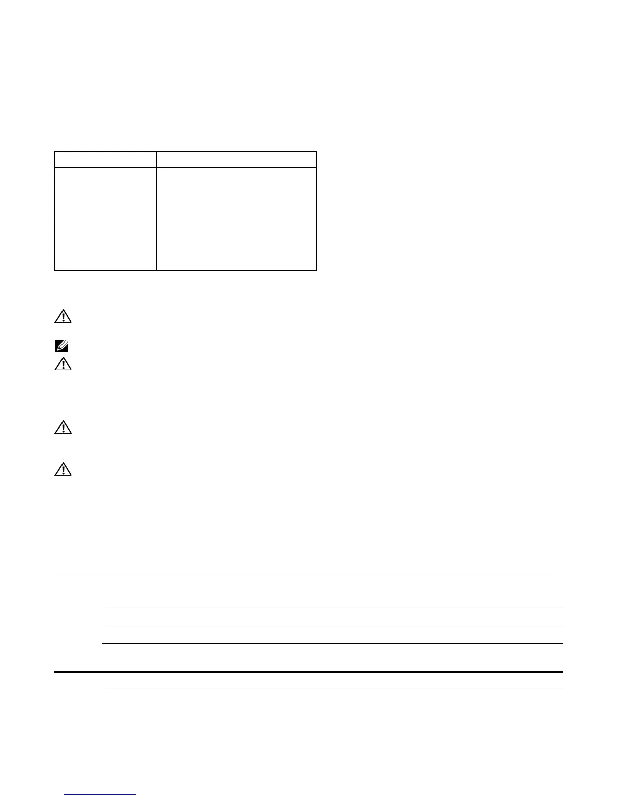
Table 7-2
lists the maximum number of ports that can be enabled for PoE per PSU.
Installing Power Supply Units
WARNING: Use only the AC power cord supplied with the AC power supply. Do not supply power to your
C150 system until the power supplies and fan tray are installed, and RPMs and line cards have been installed.
NOTE: For system input power requirements see
System Power Specifications on page 56
.
WARNING: Building Supply Notice: This product relies on the building's installation for short-circuit
(overcurrent) protection. Ensure that a fuse or circuit breaker no larger than 120 VAC, 15A U.S. (240 VAC,
10A international) is used on the phase conductors (all current-carrying conductors).
ATTENTION: Pour ce qui est de la protection contre les courts-circuits (surtension), ce produit dépend de
l'installation électrique du local. Vérifier qu'un fusible ou qu'un disjoncteur de 120 V alt., 15 A U.S. maximum
(240 V alt., 10 A international) est utilisé sur les conducteurs de phase (conducteurs de charge).
WARNUNG: Dieses Produkt ist darauf angewiesen, daß im Gebäude ein Kurzschluß- bzw.
Überstromschutz installiert ist. Stellen Sie sicher, daß eine Sicherung oder ein Unterbrecher von nicht mehr
als 240 V Wechselstrom, 10 A (bzw. in den USA 120 V Wechselstrom, 15 A) an den Phasenleitern (allen
stromführenden Leitern) verwendet wird.
You can install any power supply into any power supply slot. Dell Force10 recommends installing power
supplies starting from the left side, top row of the chassis, leaving no blank slots between units.
To install an AC power supply:
Table 7-2. PoE Ports per Power Supply Unit
Power Supply Units Maximum Number of PoE Ports
1—
2—
396
4 192
5 PoE Redundancy
6 PoE Redundancy
Step Task
1 Verify the switch is in the OFF (left) position.
2 Secure the retaining latch in the unlatched position by tightening the screw into the threaded hole (
Figure 7-2
).
3 Slide the power supply into the top left-most power supply slot. See
Figure 7-1
for the correct orientation.
4 Plug the AC power cord into the power receptacle in the face of the power supply. See
Figure 7-2
for the location
of the receptacle.
5 Lower the retaining latch, and tighten it into place (
Figure 7-2
).
6 Plug the power cord into an AC power outlet.