30 | Installing DC Power Entry Modules
www.dell.com | support.dell.com
• Rated for 60A service to allow for a fully loaded C150 system per NEC in the United States or
internationally, per local safety codes.
• Limit voltage drop across the cable length to 0.5V or less.
Apply a coat of anti-oxidant paste to unplated metal contact surfaces before you make the cable
connections. File unplated connectors, braided straps, and bus bars to a shiny finish. It is not necessary to
file and coat tinned, solder plated, or silver-plated connectors or other plated connection surfaces, such as
those on the PEM studs.
NOTE: Take precautions against over-tightening the screws or nuts on this device.
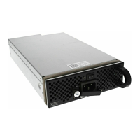
Figure 8-1. DC PEM Faceplate
Installing a DC PEM
Step Task
1 Turn the remote power source (the circuit breaker panel) to the OFF position.
2 Turn the over-current switch (located on the PEM front panel) to the OFF position.
3 Loosen the PEM safety cover retaining screw and remove the cover
(Figure 8-1)
.
Retaining Latch
Over-Current
Switch
Status LED
Handle
PEM Safety Cover
Grounding
Stud
fn0
013lp
 Loading...
